
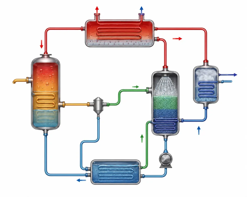
The Vapour absorption refrigeration cycle or VAR is a thermodynamic cycle that can be used to transfer heat from a low temperature space to high temperature environment by using heat as a primary energy source instead of a mechanically driven compressor as in case of a vapour compression refrigeration cycle. The vapour absorption refrigeration cycle uses an absorber, solution pump, generator and a pressure reducing valve, where the pump utilizes very little amount of mechanical work. The heat supplied to the generator drives the refrigeration process.
Table of Contents
Main components of Vapour Absorption Refrigeration Cycle
Evaporator
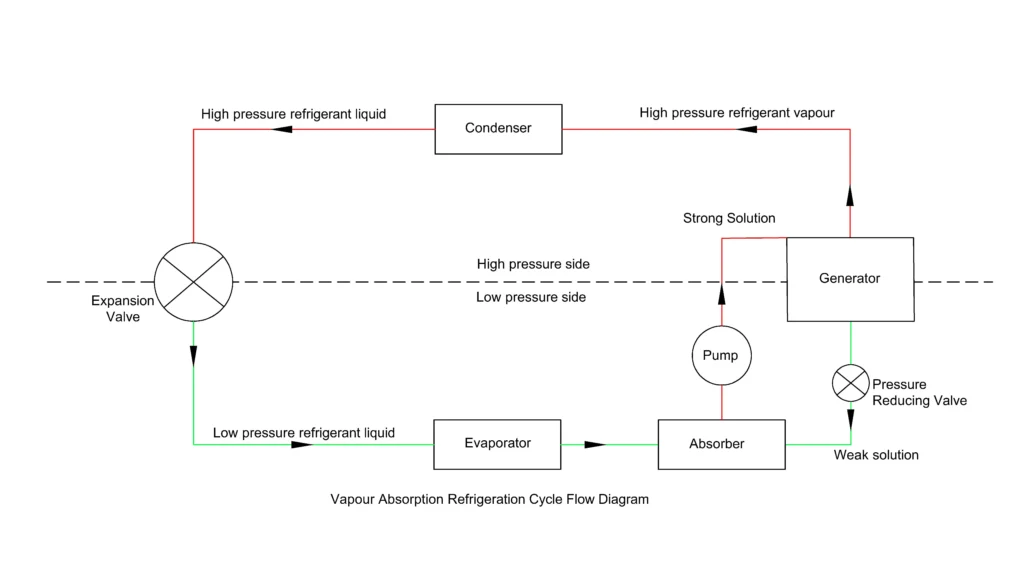
The evaporator is the component in an Vapour Absorption Refrigeration Cycle, where the refrigeration effect is produced. The low-pressure liquid refrigerant enters the evaporator and absorbs the heat from the refrigerated space. As the heat is absorbed by the refrigerant, it evaporates into vapour. In ammonia-water system, the ammonia evaporates at low pressure, while with lithium bromide- Water system, water acts as the refrigerant. The refrigerant vapour then flows into the absorber.
Absorber
The absorber receives the low pressure, vapourised refrigerant from the evaporator and absorbs it into the absorbent solution. This process of absorption releases heat, which is usually removed by cooling water or air, to maintain effective absorption. The leftover solution after the process of absorption is called strong solution which contains high concentration of absorbed refrigerant. The solution is then sent to the generator by pump.
Solution Pump
The solution pump raises the pressure of the strong solution from the absorber and sends it to the generator. Since the strong solution is in the liquid state, the pump usually requires less mechanical work compared to the compressor of the vapour compression refrigeration cycle, which is the major advantage of Vapour Absorption Refrigeration Cycle.
Generator
The generator is that component of the Vapour Absorption Refrigeration Cycle where heat is added from external sources like steam, waste heat, solar energy to the strong solution. The heat causes the refrigerant to separate from the absorbent as the refrigerant will vapourize. The high-pressure refrigerant vapour then flows through the condenser and the remaining weak solution returns to the absorber through a pressure reducing valve.
Condenser
The high-pressure refrigerant vapour enters the condenser after leaving the generator. The vapour condenses back to liquid after rejecting its heat to the cooling water or air and forms a high-pressure liquid refrigerant, which than flows towards the expansion valve.
Expansion Valve
It is through the expansion valve that the high-pressure liquid refrigerant depressurizes before entering the evaporator. The thermodynamic process involved is throttling or nearly isenthalpic. The liquid refrigerant flashes into vapour as the pressure reduces, producing low temperature liquid vapour mixture that enters the evaporator and absorbs the heat and completes the cycle.
Common working fluids used in Vapour Absorption Refrigeration Cycle
The Vapour Absorption Refrigeration Cycle primarily uses two working fluid pairs, they are ammonia-water(NH3-H2O) and Lithium bromide – Water pair (LiBr-H2O). The selection of the pair depends upon the evaporator temperature and applications.
Ammonia-Water Pair (NH3-H2O)
In this pair, the ammonia (NH3) is the refrigerant and water is the absorbent. This pair is suitable for low temperature refrigeration which includes applications below 0° Cand is commonly used in industrial refrigeration and cold storage systems.
The reaction at the absorber is
NH3(g)+H2O(l)→NH3-H2O(aq)+QLib
The reaction at the generator is
NH3-H2O(aq)+QG→NH3(g)+H2O(l)
Lithium Bromide- Water (LiBr-H2O)
In this pair, the water (H2O) is the refrigerant and lithium bromide (LiBr) is the absorbent. This pair is widely used in air conditioning and chilled-water systems. This pair cannot normally operate below 0° C as the refrigerant, water will freeze below 0° C.
The reaction at the absorber is
H2O(g)+LiBr(aq)→LiBr-H2O(aq)+QA
The reaction at the generator is
LiBr-H2O(aq)+QG→H2O(g)+LiBr(aq)
NB: It may be noted that these stoichiometric chemical reactions are only representations of the absorption and generation process. In actual case, the calculation of the components includes mass balance, refrigerant concentration, and enthalpy.
COP Of Vapour Absorption Refrigeration Cycle
COPVAR=QAbsorbed/(QSupplied+WPump)
QAbsorbed is the refrigerating effect produced.
QSupplied is the heat supplied at the generator and,
WPump is the work done by the pump, which is very small compared to the heat supplied.
The typical value of the COP for Vapour Absorption Refrigeration Cycle is 0.6 to 0.8 and for Vapour Absorption Refrigeration Cycle with double effect, the COP can improve to 1 to 1.3.
Single effect and Double effect Vapour Absorption Refrigeration Cycle
In a single effect system, heat is supplied once to the generator to produce the required cooling effect.
But in case of double effect Vapour Absorption Refrigeration Cycle, the heat from condensation of refrigerant from the high temperature generator is used to provide heating to additional low temperature generator. The supplied heat at the high pressure generator is used more effectively in 2 generators, increasing the COP of the cycle to 1-1.3.
Advantages of Vapour absorption refrigeration cycle
Utilization of waste heat
It can operate by using the waste heat from industrial processes, exhaust gases and power plants.
Utilization of multiple heat sources
This cycle can be driven by any source of heat be it steam, natural gas, hot water, solar energy or waste heat.
Very low electrical power consumption
The pump which increases the solution’s pressure, takes only a little mechanical work, making the power consumption very low.
Few moving parts
Only the pump has the moving parts and the rest of the system has no moving parts, reducing the mechanical wear and requirement of maintenance is also low.
Suitable for co-generation
Waste heat from CHP plants can be used to produce the cooling effect.
Vapour Absorption vs Compression Refrigeration Cycle
| Parameter | Absorption Refrigeration | Vapour Compression Refrigeration |
| Driving Energy | Heat | Mechanical work (electric motor) |
| Main Compression Device | Absorber + Pump + Generator | Compressor |
| COP | Lower (≈0.6–1.2) | Higher (≈2–6) |
| Electricity Consumption | Very low | High |
| Initial Cost | Higher | Lower |
| Maintenance | Lower (fewer moving parts) | Moderate |
| Best Applications | Waste heat and large cooling systems | Domestic, commercial, and industrial refrigeration |
References
- A Review of Absorption Refrigeration Technologies
- Absorption Cooling Systems – Review of Various Techniques for Energy Performance Enhancement
This article is a part of thermal system, where other related articles are discussed.