
What is Diesel Cycle?
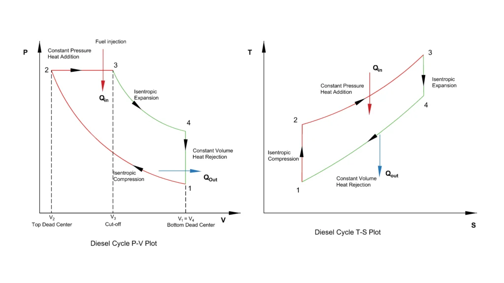
The Diesel Cycle is an ideal thermodynamic cycle which is used to model the operation of a compression ignition or CI engines. In thermodynamics, ideal Diesel cycle assumes air, which behaves as an ideal gas and represents the combustion and heat addition processes, hence is an air standard cycle. The Diesel cycle consists of four thermodynamic processes as is the case with Otto Cycle, with a difference in the process of heat addition. In Diesel Cycle, heat is added at constant pressure process rather than at constant volume.
Table of Contents
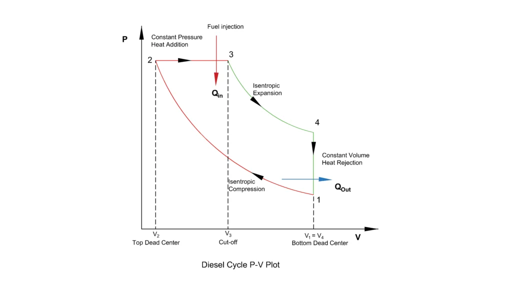
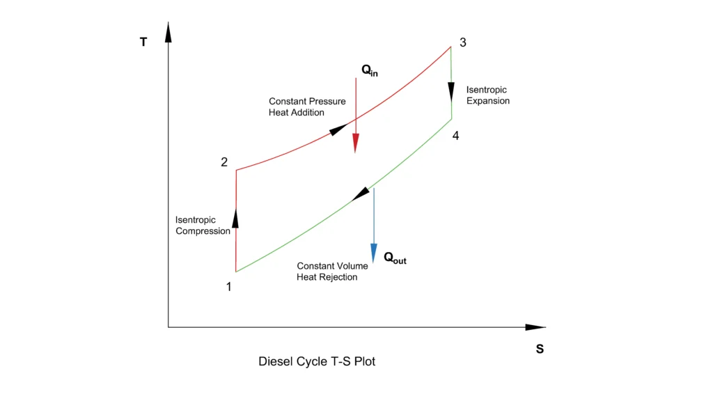
PV and TS Diagram of Diesel Cycle
Thermodynamic processes of Diesel Cycle
Isentropic Compression (1-2)
During the isentropic compression process, air is compressed from state 1 to state 2 as the piston moves from bottom dead center to top dead center in the cylinder, reducing the cylinder volume. No transfer of heat takes place during the process, which makes it reversible and adiabatic. As the volume decreases inside the cylinder, the pressure and the temperature of the air increases significantly. This high temperature of the air attained due to compression is what makes the fuel ignite in actual Diesel engine.
For process 1-2,
Constant pressure Heat Addition (2-3)
From state 2 to state 3, heat is added at constant pressure. In the actual Diesel engine, this idealized process represents the fuel injection and combustion. As the fuel is injected into the cylinder, combustion starts because if high temperature of the compressed air. The gases of combustion expand, pushing the piston and thus increasing the volume while maintaining the pressure constant during the heat addition.
Cut off ratio ρ = V3/V2 is the ratio of the volume at the end of heat addition to the volume at the initiation.
During process 2-3, Heat added,
Also,
Isentropic Expansion (3-4)
During the process, the high temperature and high-pressure gases expand in the cylinder from state 3 to state 4. The expansion of the gases pushes the piston downwards, producing the useful wor. No heat is transferred from or to the surrounding during this process and the pressure and the temperature decreases as the volume increases.
During the process 3-4,
Constant Volume Heat Rejection
The heat of the diesel cycle is rejected from state 4 to state 1 by constant volume process. During this process, the volume remains unchanged while the temperature and the pressure reduce. This returns the woring fluid to initial state, there by completing the ideal diesel cycle.
During this process, the heat rejected is given by
Efficiency of the Diesel cycle
The net work done during the Diesel cycle considering unit mass is given by
Therefore, the thermal efficiency of the Diesel cycle is given by
Now substituting the values of
into the above equation, we get
What is cut-off ratio in a Diesel cycle?
The cut-off ratio is an important parameter in the Diesel cycle which is used to describe the heat addition process in the ideal cycle. It is basically the ratio of the volume of the cylinder at the end of the heat addition to the volume at the beginning of the heat addition.
Where V2 is the volume of at the beginning of the constant pressure heat addition and V3 is the volume at the end of the process. The cut-off ratio indicates how long the heat addition continues as the piston moves towards the bottom dead center during the expansion stroke. A higher cut-off ratio indicates that the heat is added over a greater volume of the cylinder. For a given compression ratio, higher cut-off ratio results in lower Diesel cycle thermal efficiency as heat addition in the later or larger part of the expansion stroke makes the heat addition less effective by lowering the average temperature of heat addition for producing work.
Why Does the Diesel Cycle Use Constant Pressure Heat Addition?
The Diesel cycle assumes constant pressure heat addition because the fuel injection and the combustion of the diesel in a real engine takes a finite amount of time and not happens instantaneously. During the heat addition, the piston moves towards the bottom dead center causing the volume of the cylinder to expand. At the same time, the combustion of the diesel, releases the heat, which tends to increase the pressure inside the cylinder. The volume expansion offsets this pressure rise, allowing the combustion process to be at nearly constant pressure. Typically, the cut-off ratio of diesel cycle varies between 1.5 to 2.5
Compression Ratio in Diesel Cycle
The compression ratio in diesel cycle represents the ratio of maximum cylinder volume to the minimum volume and is expressed as
Where V1 is the cylinder volume at the beginning of the compression and V2 is the cylinder volume at the end of the compression. In the Diesel Cycle only air is compressed before the injection of fuel and it thus allows for a higher compression ratio without the risk of premature combustion of fuel. The high compression raises the pressure and temperature inside the cylinder which auto ignites the injected diesel fuel. Typically, the compression ratio of Diesel cycle varies between 14:1 to 25:1.
Reference
- NPTEL — Air Standard Diesel Cycle
- R. K. Rajput — Engineering Thermodynamics
- V. Ganeshan — Internal Combustion Engines
This article is a part of thermal system, where other related articles are discussed.