
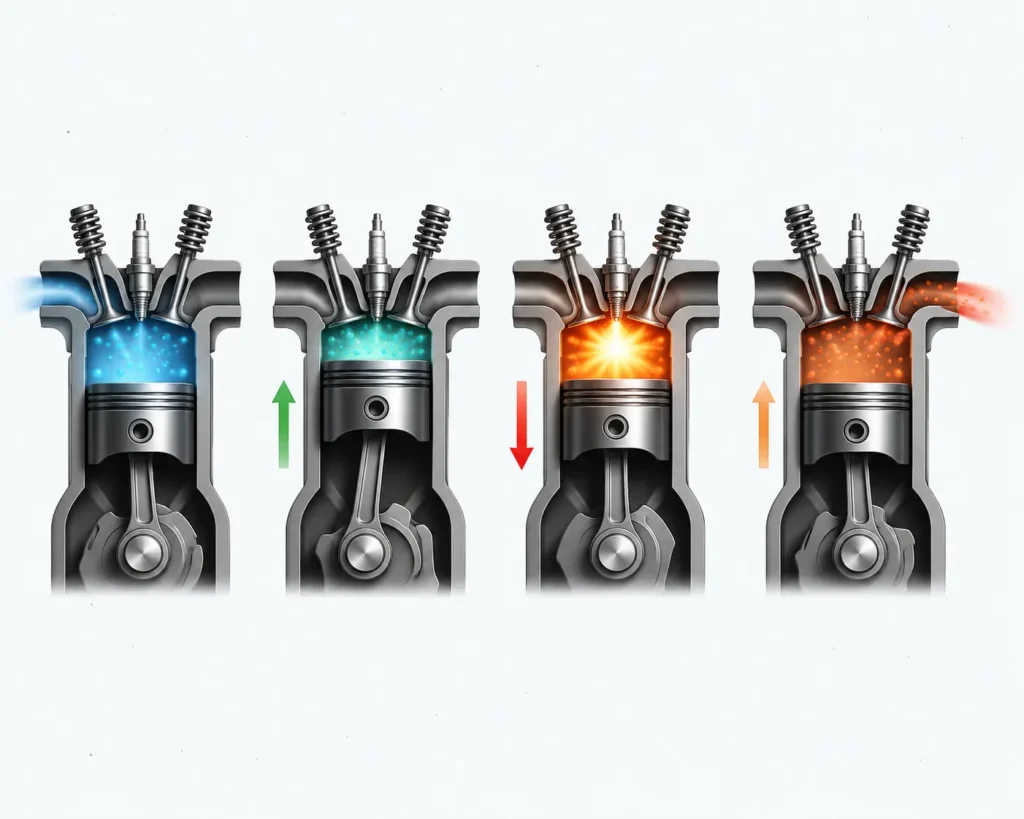
The Otto cycle is an ideal thermodynamic cycle, which forms the basis of conversion of the chemical energy of fuel into useful mechanical work with a spark ignition internal combustion engine. Otto cycle was developed by the German Engineer, Nicolaus August Otto in the year 1876. It is an air standard cycle, assuming air as the working fluid following idealized thermodynamic behavior.
The Otto cycle represents the operating principle of gasoline and petrol engines used in most passenger cars and bikes. It consists of four reversible processes viz isentropic compression, constant volume heat addition, isentropic expansion and constant volume heat rejection, which together converts the heat released from combustion of the fuel (chemical energy) into mechanical work. Unlike the real engines, the ideal otto cycle neglects heat loss, friction, incomplete combustion and pumping losses, predicting a higher thermal efficiency.
Table of Contents
PV and TS diagram of the Otto cycle
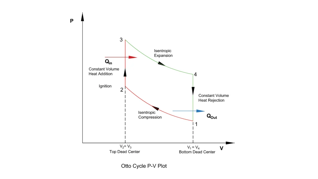
The pressure-volume or PV diagram represents the four thermodynamic processes of the Otto cycle. The curve 1-2 represents the isentropic compression during which the pressure rises and volume decreases. 2-3 represents a constant volume heat addition caused by the combustion producing a sharp increase in pressure. The curve 3-4 shows the isentropic expansion, where the pressure reduces and the gas produces the work. Finally, 4-1 represents the constant volume heat rejection, returning the working fluid to initial condition of the cycle. The area enclosed by the PV diagram represents the net work output of the cycle.
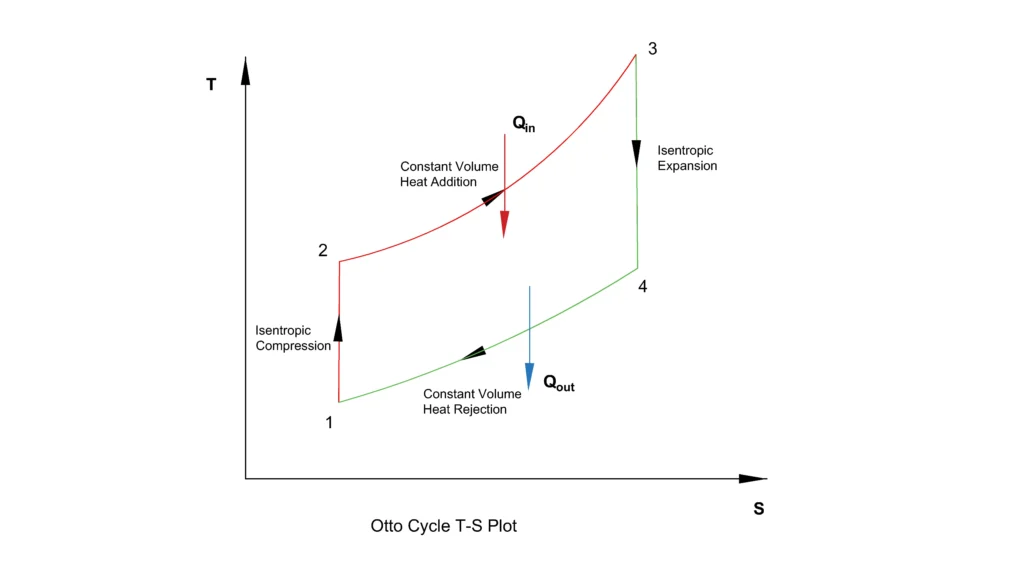
The temperature entropy or TS diagram shows the heat transfer characteristics of the cycle. During 1-2 and 3-4 processes, the entropy remains constant as no heat is transferred. The constant volume heat addition 2-3 increases both the temperature and entropy, while the process 4-1, constant volume heat rejection decreases both.
Thermodynamic processes of the Otto cycle
The ideal Otto cycle consists of four reversible thermodynamic processes which models the operation of a spark ignition gasoline engine. These processes are represented on the Pressure-Volume (PV) and Temperature-Entropy (TS) diagrams above.
Isentropic compression (1-2)
The cycle begins with an isentropic (reversible adiabatic) compression, where the piston moves up from the bottom dead center to the top dead center of the cylinder, compressing the air fuel mixture. Because the process is isentropic, no heat is transferred to or from the surroundings. As the volume of the cylinder decreases, both the pressure and temperature of the air fuel mixture rises significantly, while the entropy remains constant.
For the 1–2 process of the Otto cycle, the compression is reversible adiabatic (isentropic). Therefore,
where:
- P = Pressure
- V = Volume
The work done during the compression process is
Since
pressure can be written as
Substituting into the work equation,
Taking the constant outside the integral,
Integrating,
Hence,
Using the isentropic relation,
Substituting,
Since
the equation simplifies to
or equivalently,
Since compression requires external work,
indicating that work is done on the working fluid.
Constant volume heat addition 2-3
At the end of the compression stroke, the spark plug initiates a spark, which ignites the compressed air fuel mixture. The combustion is assumed to occur instantaneously at constant volume, meaning the position of the piston remains momentarily at the top dead center, during heat addition, maintaining the volume constant. Since, the volume does not change during the process, the pressure and temperature of the working fluid increases sharply.
Heat supplied during the process,
Isentropic Expansion 3-4
The high pressure and high temperature combustion gases after the heat addition at constant volume, expands and pushes the piston down wards from the top dead center to the bottom dead center, producing the power stroke. As the gas expands isentropically, the pressure and the temperature drops, while a large portion of the internal energy is converted into useful mechanical work delivered to the crank shaft. This process in the Otto cycle produces the work.
The work done during the expansion process is
Since
pressure can be written as
Substituting into the work equation,
Taking the constant outside the integral,
Integrating,
Hence,
Using the isentropic relation,
Substituting,
Since
the equation simplifies to
or equivalently,
Since expansion produces useful work,
indicating that work is done by the working fluid on the piston.
Constant volume heat rejection 4-1
After expansion, the remaining heat of the working fluid is rejected through constant volume heat rejection process. The volume of the cylinder remains unchanged, while the pressure and temperature drops, returning the air to its initial thermodynamic state. In an actual engine, this process corresponds to the exhaust process, where the burned gases leave the cylinder. In ideal Otto cycle, this process closes the cycle and prepares the working fluid for the next compression process.
Heat rejected,
Thermal efficiency of the Otto Cycle
The thermal efficiency of an heat engine is defined as
Since,
the thermal efficiency becomes
or,
Heat Supplied (Process 2–3)
During the constant-volume heat addition process,
Heat Rejected (Process 4–1)
During the constant-volume heat rejection process,
Substituting into the Efficiency Equation
Cancelling m and Cv,
Applying the Isentropic Relations
For the compression process (1–2),
Since the compression ratio is
Similarly, for the expansion process (3–4),
Since,
or,
Substituting,
into
We get,
Multiplying the numerator and denominator by rγ-1,
Cancelling the common term we get,
Now, substituting it into the efficiency equation,
or
where
- r =V1/V2is the compression ratio,
- γ = Cp/Cv is the ratio of specific heats.
Factors affecting the thermal efficiency of the Otto cycle
The thermal efficiency of the Otto cycle depends both on the thermodynamic characteristics and the operating conditions of the engine. Though the ideal Otto cycle predicts the efficiency using the compression ratio and ratio of specific heat, the performance of a real engine is influenced by combustion, heat transfer and mechanical losses.
Compression Ratio (r)
The efficiency of the Otto cycle is affected the most by the compression ratio, r. A high compression ratio increases the temperature and pressure of the air fuel mixture, allowing more heat to be converted into useful work, thus increasing the thermal efficiency. However, in real engines, the maximum compression ratio is limited by the engine knocking.
Ratio of specific heat (γ)
The ratio of specific heat also influences the efficiency of the Otto cycle as higher value of γ increases the theoretical thermal efficiency as the working fluid undergoes a larger temperature change during the isentropic compression and expansion. Since, γ depends on the properties of the working fluid and temperature, it cannot be increased significantly in the practical engines.
Heat Loss
In actual engines, a portion of the heat released during the combustion is transferred to the cylinder walls, piston and cooling system instead of being converted to work. This reduces the peak gas temperature and pressure lowering the thermal efficiency.
Quality of combustion
The ideal Otto cycle assumes instantaneous and complete combustion. However, in practical engines, poor air fuel mixture, improper timing of ignition and flame propagation losses reduces the amount of energy released as part of the air fuel mixture remains unburnt, thereby decreasing the efficiency.
Engine Friction
Mechanical friction between the moving component such as piston, piston ring, crank shaft, bearings and valve trains consumes a part of the power produced during the expansion of the working fluid. These frictional losses reduce the brake power delivered at the crank shaft, reducing the thermal efficiency.
Reference
- The Otto Cycle Engine: A Mathematical Model for Combustion
- A Thermodynamic Analysis of the Rate of Rise of Pressure in the Otto Cycle
This article is a part of thermal system, where other related articles are discussed.