
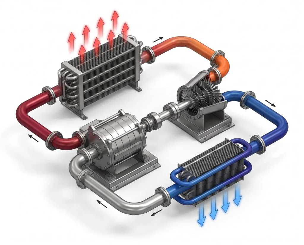
The Reverse Brayton cycle or Bell Coleman cycle is an air refrigeration system, which is reversed from the Brayton cycle for producing refrigeration and cooling effect. Instead of converting the heat into mechanical work, in reverse Brayton cycle, mechanical work is consumed to transfer heat from a low temperature region to the high temperature surrounding.
The reverse Brayton cycle uses air as the working fluid and operates via isentropic compression, heat rejection at constant pressure, isentropic expansion and constant pressure heat absorption. The reverse Brayton cycle being simple and for reliable operation is widely used in environment control of aircraft, gas liquefaction and cryogenic cooling applications.
Table of Contents
Working principle of the reverse Brayton cycle
The reverse Brayton cycle operates by circulating air through four thermodynamic processes to transfer heat from a low temperature region to high temperature surroundings. During the cycle, the working fluid, usually air is compressed, then is cooled at constant pressure, expanded to a low temperature and then made to absorb heat from the refrigerated space. After absorbing the heat, the working fluid returns to the compressor making the cycle complete. The continuous repletion of these processes provides a steady and effective cooling.
PV and TS diagram of reverse Brayton cycle
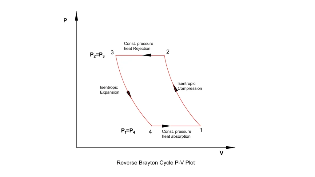
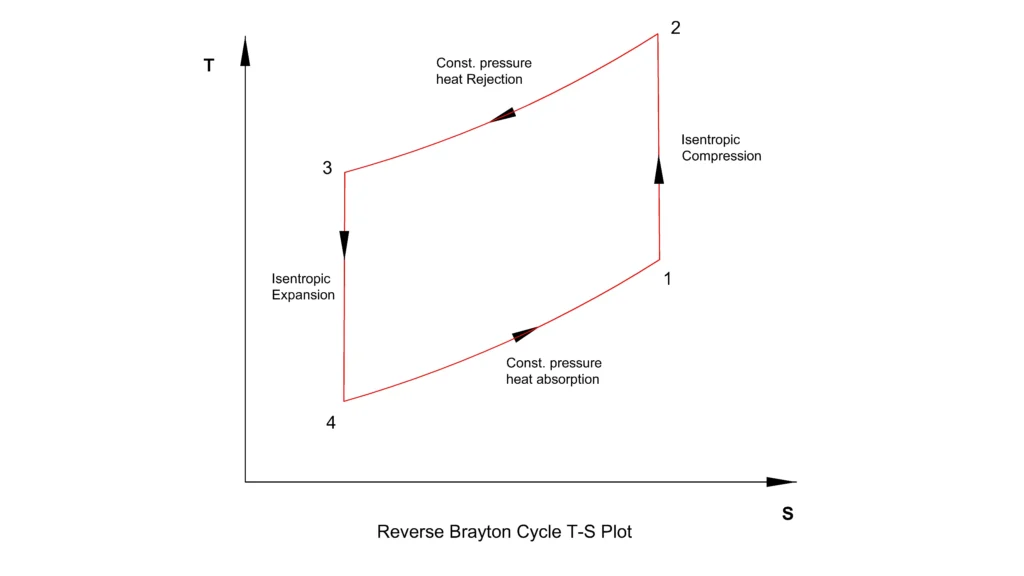
The cycle’s direction is just opposite to the power Brayton cycle. The area enclosed by the TS diagram represents the work input required for the cycle. It may be noted that here, heat rejection occurs before expansion and heat absorption occurs after expansion of the working fluid.
Thermodynamic processes
Isentropic compression 1-2
The low pressure air, after absorbing the heat from the refrigerated space, enters the compressor and is compressed isentropically. During the compression, the pressure as well as the temperature increases significantly with constant entropy. The compressor takes mechanical work, making it the primary energy input to the cycle.
Constant pressure heat rejection 2-3
The high pressure high temperature working fluid from the compressor outlet flows through a heat exchanger to reject the heat to the surrounding environment nearly at constant pressure. As the heat is removed, the temperature falls down, while the pressure remains constant.
Isentropic Expansion 3-4
The cooled high pressure working fluid adiabatically expands through an expansion turbine. During this expansion, the working fluid makes the turbine to produce shaft work, causing its pressure and temperature to significantly reduce. The working fluid thus leaves the turbine at a temperature lower than that of the refrigerated space for an efficient heat transfer or heat absorption.
or, since P4=P1 and P3=P2, rp =P2/P1,
Constant pressure heat absorption 4-1
The cold, low pressure working fluid passes through the refrigerated space or evaporator, where it absorbs the heat from the space at nearly constant pressure. As the gas or air gains heat, its temperature rises and proceeds towards the compressor for completing the cycle.
The net result of providing mechanical work to the compressor is transfer of heat from low temperature region to high temperature region.
Net Work input
As the compressor requires more work than the turbine produces, the net work input for the reverse Brayton cycle becomes
For an ideal gas,
Coefficient of performance of reverse Brayton cycle
The COP of the reverse Brayton cycle is defined as
Substituting the above equations,
The typical COP of reverse Brayton cycle is lower than vapour compression system as the working fluid of reverse Brayton cycle has lower heat capacity per unit volume and there is also no phase change involved.
Where should the reverse Brayton cycle be used?
The reverse Brayton cycle or the Bell-Coleman cycle is selected when reliability, lightweight equipment, continuous operation and very low temperatures are the priority compared to achievement of high coefficient of performance. Unlike the Vapour compression refrigeration cycle, air is taken as the working fluid, which eliminates the need for refrigerants with environmental concerns. The reverse Brayton cycle also does not have any phase change of the working fluid.
Reverse Brayton cycle is chosen for
- Aircraft environment control system which requires lightweight, compact and reliable cooling system.
- Cryogenic cooling with temperature below 150 °C for liquid nitrogen and liquid oxygen production.
- Gas liquefaction plant which requires continuous cooling as is provided by reverse Brayton cycle.
- In medical, aerospace and laboratory where oil free refrigeration is essential.
- Nontoxic and non-flammable working fluids such as air, helium or nitrogen is preferred.
Do not chose reverse Brayton cycle
- For domestic refrigeration and air conditioners where high COP is the priority.
- Industrial refrigeration, where maximum energy efficiency is the primary objective.
- Applications where space and weight are not critical. COP of reverse Brayton cycle typically varies between 0.3 to 1, which is on the lower side.
Reference
- NASA NTRS – Reverse Brayton Cycle with Bladeless Turbo Compressor for Automotive Environmental Cooling
- NASA NTRS – 20 W 20 K Reverse Turbo-Brayton Cycle Cryocooler Testing and Applications
This article is a part of thermal system, where other related articles are discussed.