
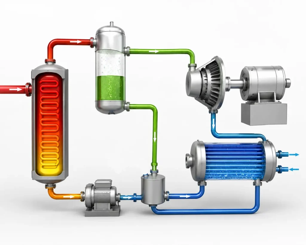
Kalina Cycle is an advanced thermodynamic cycle, which converts the low grade thermal energy to electricity by using binary working fluid that is ammonia and water mixture instead of pure water or organic fluid. The Kalina cycle was developed in early 1980s to improve the efficiency of power generation from low temperature heat sources by Russian Engineer Alexander Kalina.
Table of Contents
Unlike the conventional Rankine cycle, ammonia and water, used as the working fluid in Kalina cycle, evaporates and condenses back over a range of temperature rather than a constant temperature. This variable boiling characteristics provides a better thermal match with the heat source, reducing the irreversibilities of the heat transfer between the low grade heat source and the working fluid, improving the heat transfer efficiency. These improvements makes the Kalina cycle recover more energy from the waste heat, geothermal sources and other low grade heat sources.
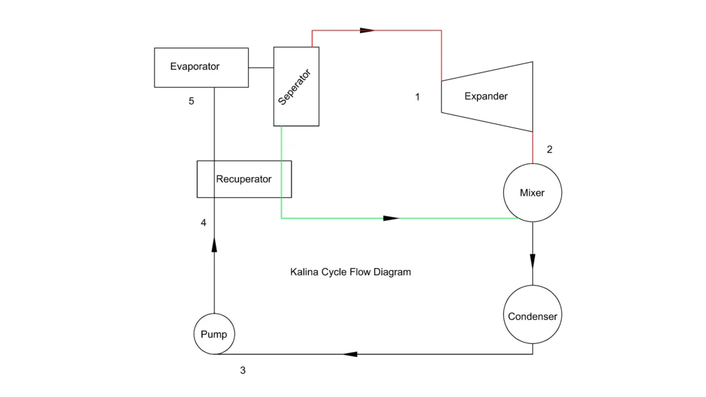
Major components of a Kalina cycle system
Feed Pump
The feed pump increases the pressure of the working fluid, that is ammonia-water mixture with typically 70-90% ammonia by weight, from approximately 2-5 bar at 30-40°C to 40-120 bar depending on the temperature of the heat source. The fluid mixture remains in subcooled liquid state at the end of pumping action.
Heat recovery boiler or Evaporator
The pressurized liquid absorbs heat from the external source typically at 100 to 400°C in the heat recovery boiler. The working fluid is heated to 120-350 °C at 40-120 bar, which produces two phase ammonia-water mixture before entering the separator.
Vapour separator
The vapour separator operates at the same pressure as that of the evaporator. It splits the working fluid mixture into ammonia rich saturated vapour and ammonia lean liquid. The vapour separator is a vertical pressure vessel where the mixture enters and gets separated by gravity action.
Since, ρLiquid > ρVapour, the dense liquid falls to the bottom and the ammonia rich vapour rises to the top. From the upper outlet, the ammonia rich vapour with a concentration of 85-95% leaves the separator and moves towards the Turbine. The water rich liquid or ammonia lean liquid passes through the lower outlet bypassing the turbine, flowing through heat exchangers and mixing with the turbine exhaust.
Turbine
The high pressure ammonia rich vapour expands through the turbine from 40-120 bar approximately to 2-5 bar with decreasing temperature from 120-350°C to 40-100°C. The working fluid exits the turbine as wet vapour or slightly superheated vapour producing shaft power.
Recuperator or Internal Heat exchanger
The recuperator recovers heat from the hot lean ammonia liquid from the separator and transfers it to cold ammonia-water mixture before it enters the evaporator. Instead of wasting this heat, the recuperator reheats the working fluid and reduces the external heat input, thereby increasing the thermal efficiency of the cycle.
Mixer or Absorber
After the expansion in the turbine, the rich ammonia vapour and the water rich liquid from the recuperator are recombined in the mixer. The mixer restores the original ammonia concentration before the condensation and pumping.
Condenser
The ammonia-water fluid from the mixer rejects the heat to cooling water or air and condenses at 2-5 bar and 20-40 °C, forming saturated or slightly subcooled liquid ready to be pumped to the evaporator pressure.
Why Kalina cycle is more efficient?
The Kalina cycle achieves higher efficiency than conventional Rankine cycle and Organic Rankine Cycle by using the ammonia-water mixture, which evaporates and condenses over a temperature range rather than a constant temperature. This variable phase change behaviour provides a closer temperature match between the heat source and the working fluid, which reduces the average temperature difference during heat transfer. This results in less entropy generation, minimizing the irreversilities, leading to lower exergy losses and improved thermal efficiency.
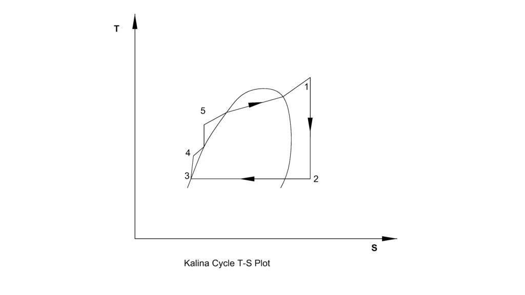
The Kalina cycle extracts more useful energy from the same heat source, specially with low temperature waste heat and geothermal sources. The Kalina cycle performs the best with heat sources in the range of 100-250°C, where it often outperforms the conventional and organic Rankine cycle.
Why is Ammonia used in the Kalina Cycle?
Ammonia is used in the Kalina cycle because of the following:
Low boiling point: Pure ammonia boils at -33.3°C at 1 atm pressure, allowing it to vaporise using the low heat sources 100-250°C.
Better temperature matching: Ammonia mixed with water, boils and condenses over a temperature range and not at constant temperature. The temperature difference between the heat source and working fluid is much smaller, which lowers the entropy generation. This makes the energy recovery efficient.
Higher thermal efficiency for the cycle: The variable phase change temperature reduces the irreversibilities and exergy losses, increasing the cycle efficiency.
High latent heat of vaporization: Ammonia absorbs a large amount of heat during vaporisation, allowing large amount of thermal energy to be transferred per unit mass.
High Vapour pressure: At 100 °C, ammonia usually has a saturation pressure of 62 bar, providing sufficient pressure for efficient turbine expansion.
High heat transfer properties: The ammonia water mixture has a high heat transfer coefficient, which reduces the required size of heat exchanger.
No ozone depletion: Since, ammonia has a ozone depletion potential of 0 and global warming potential of 0, it makes it environment friendly working fluid.
Readily available and inexpensive: Ammonia is readily available and widely used in industrial sectors making it cost effective for large scale power generation.
References
- Zhang, X., He, M., & Zhang, Y. (2012) – A Review of Research on the Kalina Cycle
- Nag, P. K., & Gupta, A. V. S. S. K. S. (1998) – Exergy Analysis of the Kalina Cycle
This article is a part of thermal system, where other related articles are discussed.