
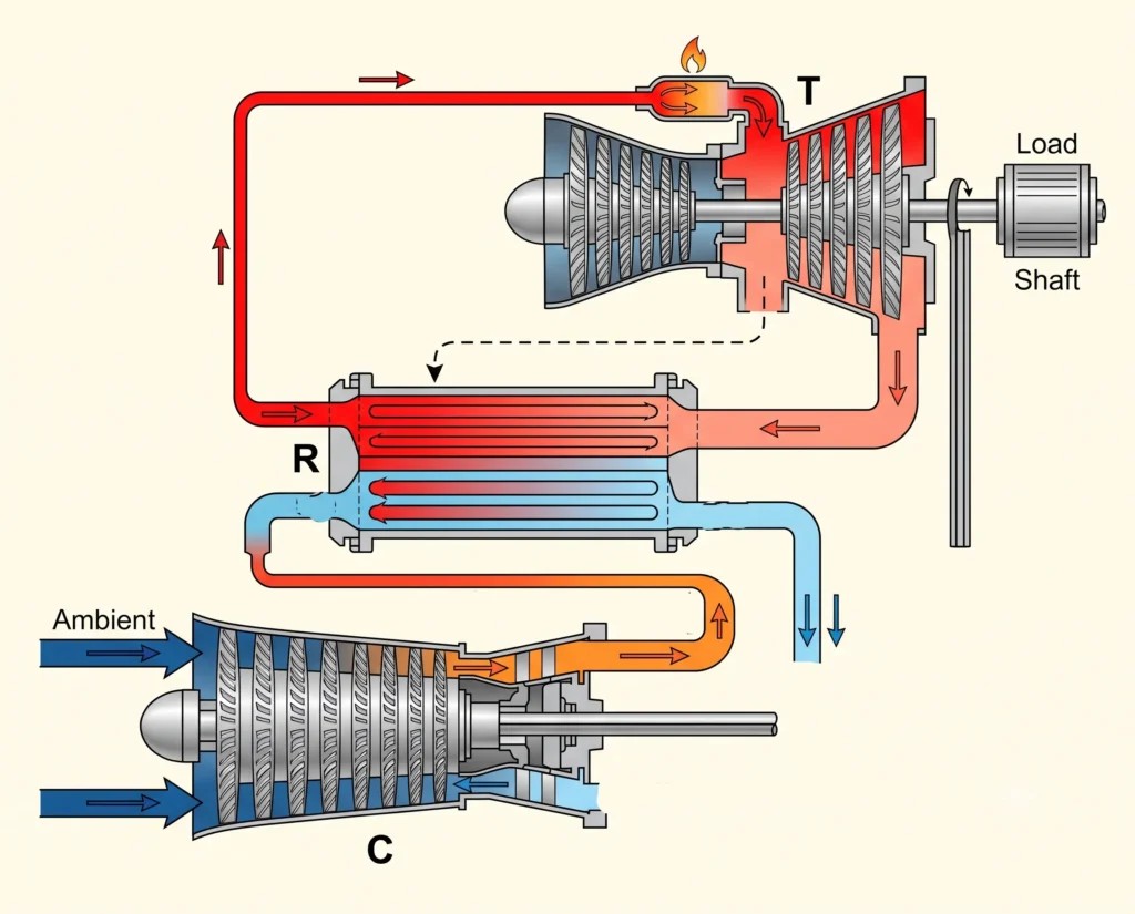
A regenerative Brayton cycle is basically a modified version of simple Brayton cycle, which improves the cycle’s thermal efficiency by recovering the heat present in the turbine’s exhaust. The turbine’s exhaust is made to pass through a regenerator, which is a heat exchanger also called as recuperator. This transfers the heat in the turbine’s exhaust to the compressed air, leaving the compressor before entering the combustor. This extraction of the waste heat from the turbine’s exhaust results in less fuel requirement to raise the temperature of the compressed working fluid to desired turbine inlet temperature.
Table of Contents
Unlike the simple Brayton cycle, where most of the heat is discarded to the surroundings, the regenerative Brayton cycle uses this energy which would otherwise be wasted. The regenerative Brayton cycle is most suitable for stationary gas turbine and combined heat and power applications.
Working Principle
Just like a simple Brayton cycle, in regenerative Brayton cycle, the working fluid is compressed isentropically, increasing its pressure and temperature. But instead of flowing directly to the combustor, the working fluid enters the regenerator, where it absorbs the heat from the hot turbine exhaust. This preheating of the working fluid raises its temperature before the combustion or isobaric heat addition process.
Since, the compressed air is already heated, the fuel required in the combustor is therefore much less for the working fluid to reach desired turbine inlet temperature. Heat is then added to the working fluid at constant pressure, which is then expanded in isentropic process in the gas turbine, generating power to drive the compressor and produce useful shaft work.
After expansion, the exhaust of the turbine still has considerable thermal energy around 40% left with exhaust temperature ranging from 450 to 650°C. Instead of rejecting this to the surroundings, the exhaust passes through the regenerator, where it surrenders part of its heat to the incoming compressed working fluid. After part of the heat is recovered from the exhaust, the remaining is discharged to the atmosphere.
By recovering a part of the thermal energy from the turbine exhaust, the regenerative Brayton cycle reduces the fuel consumption and thus improves the thermal efficiency.
Components of Regenerative Brayton cycle
Compressor
In an open cycle regenerative Brayton cycle, the compressor draws in ambient air at approximately 1 bar and 15 to 35°C and compresses the air isentropically to a pressure of 5 to 20 bar depending upon the design.
Regenerator
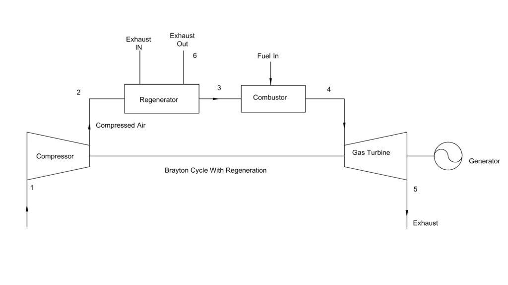
The regenerator is highly effective heat exchanger that recovers the heat from the turbine exhaust. It is usually placed after the compressor as the compressed air enters the regenerator at 180-400°C and is preheated to around 350-650°C before entering the combustion chamber. While the turbine exhaust enters the regenerator at around 650°C and leaves at 200-250°C surrendering heat to the compressed air. Modern regenerator has around 70-90% effectiveness.
Combustion chamber
The fuel is burnt in the combustion chamber along with the preheated compressed air at almost constant pressure with tolerable pressure loss of 2-8%. The combustion process raises the gas temperature to the turbine inlet temperature at around 1500°C depending upon the design of the gas turbine. As the incoming compressed air is already preheated by the regenerator, the fuel requirement thus drops by 20-30% compared to simple Brayton cycle.
Gas Turbine
The gas turbine expands the high temperature, high pressure gas insentropically from 5-20 bar to atmospheric pressure. During this process, the temperature of the gas decreases from 1500°C to around 650°C at the turbine outlet. This hot exhaust gas then passes through the regenerator as it recovers the heat from the exhaust gas before being discharged.
Thermodynamic Processes involved in Regenerative Brayton Cycle
The thermodynamic processes involved in the regenerative Brayton cycle are
Isentropic Compression 1-2: The working fluid is compressed in a compressor.
Regenerative heating 2-3: The regenerative heating is at a constant pressure process as the regenerator is a simple heat exchanger and does not involves any compression or expansion. The cold side pressure of the compressed air is not altered by the regenerator while on the hot side, the turbine’s exhaust pressure is also atmospheric before and after transferring heat to the regenerator.
Constant pressure heat addition 3-4: During this process heat is added or fuel is burnt in the combustor at constant pressure to raise the temperature of the working fluid to desired turbine inlet temperature.
Isentropic Expansion 4-5: The hot compressed air is expanded in the Gas turbine, which produces the mechanical work.
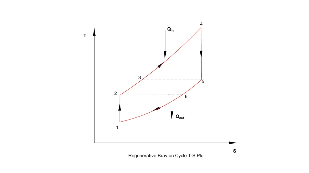
Constant pressure heat rejection 5-6: Instead of rejecting the heat in the exhaust to the surroundings, it is recovered by the regenerator to preheat the compressed air.
Constant pressure heat rejection 6-1: After rejecting the heat at the regenerator, the rest of the heat left in the exhaust is rejected directly to the atmosphere.
Thermal Efficiency
The thermal efficiency of the regenerative Brayton cycle is defined as the ratio of the net work output to the heat supplied.
Unlike the simple Brayton cycle, the compressed working fluid of the regenerative Brayton cycle is preheated before entering the combustor. Hence, the heat supplied by fuel is reduced and is expressed as
rather than
for a simple Brayton cycle.
As the preheated compressed air T3 has a temperature higher than the normal compressed air T2. Therefore, temperature rise required in the combustion chamber is less, resulting in reduced fuel consumption for same turbine and compressor work. This reduction in fuel or heat supplied increases the thermal efficiency of the regenerative Brayton cycle.
The performance of the regenerator is measured by its effectiveness, which shows how effectively the heat exchanger recovers heat from the turbine exhaust. It is defined as
where T5 is the turbine exhaust temperature and T2 is the compressor outlet temperature and T3 is the temperature of compressed air after regeneration.
The value of effectiveness ranges from 0 to 1. ‘0’ effectiveness indicates that the cycle is behaving like simple Brayton cycle with no regeneration. While ‘1’ indicates ideal regenerator in which the compressed air leaves the regenerator at the same temperature as that of the turbine exhaust, achieving the maximum heat recovery.
Condition for effective regeneration
Regeneration is only possible when the turbine’s exhaust temperature is higher than the compressor outlet temperature. That is
T5 > T2
Under this condition, heat naturally flows from the turbine exhaust to the cooler compressed working fluid.
At moderate pressure ratio of 4 to 10, the temperature of the compressed air at the outlet of the compressor is relatively low while the turbine exhaust temperature remains sufficiently high. Hence at these pressure ratios, regeneration is most effective.
However, as the pressure ratio increases beyond 15, compressor outlet temperature rises and the temperature difference between T5 and T2 becomes small, reducing the amount of recoverable heat. Hence, for high pressure ratios, the complexities and additional cost of regenerative Brayton cycle is not justified.
Reference
- ScienceDirect – Brayton Cycle Overview
- NASA Technical Reports Server – Recuperated Closed Brayton Cycle
This article is a part of thermal system, where other related articles are discussed.