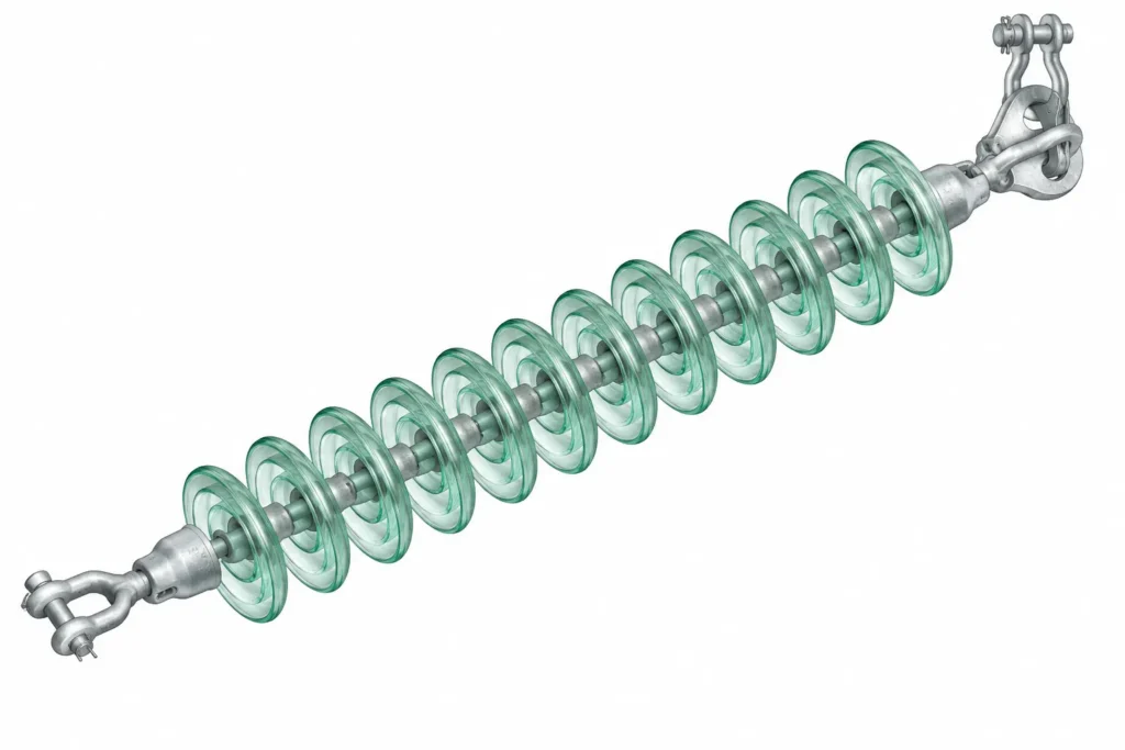
In over head transmission system, tower insulators are critical components installed on the transmission tower along with the hardware fittings, forming an insulator string. The tower insulators or the insulator string, functions to mechanically support the conductor and isolate it electrically from the tower structure so that current flow from the conductor to the tower body is prevented.
Table of Contents
Parameters on which the number of disc per insulator string is selected
System voltage: It is the nominal voltage of the system between phases (33, 66,132,220,400,..) KV. The higher is the system voltage, more is the disc required per insulator string.
Highest system voltage: It is the highest rated voltage of the system usually 1.1 times the system voltage.
Power frequency withstand voltage: It is the maximum AC voltage that an insulator can withstand for a specified time without rapture or puncture or failure.
Lightning impulse withstand voltage: It is the peak impulse voltage that the insulator can withstand without rapture, puncture or failure during a standard lightning test.
Switching surge withstand voltage: It is the transient surge in voltage which the insulator must withstand, produced because of any switching operation, fault clearing or circuit breaker operation, causing high stress in the insulators.
| Nominal Voltage | Highest System Voltage | Power Frequency Withstand Voltage (1 min RMS) | Lightning Impulse Withstand Voltage (BIL Peak) | Switching Impulse Withstand Voltage (Peak) |
| 11 kV | 12 kV | 28 kV | 75 kV | — |
| 22 kV | 24 kV | 50 kV | 125 kV | — |
| 33 kV | 36 kV | 70 kV | 170 kV | — |
| 66 kV | 72.5 kV | 140 kV | 325 kV | — |
| 110 kV | 123 kV | 230 kV | 550 kV | — |
| 132 kV | 145 kV | 275 kV | 650 kV | — |
| 220 kV | 245 kV | 460 kV | 1050 kV | 850 kV |
| 400 kV | 420 kV | 630 kV | 1425 kV | 1050 kV |
| 765 kV | 800 kV | 830 kV | 2100 kV | 1550 kV |
Creepage distance requirement: The creepage distance requirement is among the most important design criteria that decides the number of disc per insulator string. The creepage distance depends upon the pollution level of the area. The formula for the required creepage distance is as follows
Required Creepage distance (ε0) = Specific creepage distance x Highest system voltage.
Typical Specific creepage distance values based on varied levels of pollutions.
| Pollution Level | Creepage Requirement |
| Light | 16 mm/kV |
| Medium | 20 mm/kV |
| Heavy | 25 mm/kV |
| Very Heavy | 31 mm/kV |
Number of disc required per insulator string
Number of disc or elements under normal condition
Under normal conditions, no. of disc insulator per string required, η normal ≥ ε0 / ε
≥ Required creepage distance (ε0) / creepage distance of the single insulator disc(ε).
| Insulator Type | Mechanical Strength | IEC Type | Creepage Distance | Diameter × Spacing |
| Standard Porcelain Disc | 70 kN | U70BL | 295 mm | 255 × 146 mm |
| Anti-Fog Porcelain Disc | 70 kN | U70BP | 430 mm | 280 × 146 mm |
| Standard Glass Disc | 70 kN | U70BS | 320 mm | 255 × 146 mm |
| Standard Porcelain Disc | 90 kN | U90BL | 320 mm | 255 × 146 mm |
| Anti-Fog Porcelain Disc | 90 kN | U90BP | 450 mm | 280 × 146 mm |
| Standard Glass Disc | 90 kN | U90BS | 320 mm | 255 × 146 mm |
| Standard Porcelain Disc | 120 kN | U120BL | 320 mm | 255 × 146 mm |
| Anti-Fog Porcelain Disc | 120 kN | U120BP | 550 mm | 330 × 146 mm |
| Standard Glass Disc | 120 kN | U120BS | 320 mm | 255 × 146 mm |
It may be noted that required creepage distance, ε0 is calculated for medium level of pollution as per IEC 11, unless specified.
Number of disc or elements under wet condition
Under wet conditions, no. of disc required per insulator string, η wet ≥ Upf / Uw
Upf is the maximum power frequency withstand voltage of the line and;
Uw is the single disc’s power frequency withstand Voltage kV (rms) wet for 1 minute.
Number of disc or elements under lightning impulse condition
Under lightning conditions, no. of disc required per insulator string, η impulse ≥ ULi / UL
ULi is the maximum lightning impulse withstand voltage of the line and;
UL is the single disc insulator’s lightning impulse withstand Voltage.
The highest number among the three condition is considered as per electrical criterion of selection.
| Disc Insulator | Wet Power Frequency Withstand Voltage | Lightning Impulse Withstand Voltage |
| Standard 70 kN Disc | 35 kV | 75 kV |
| Standard 90 kN Disc | 35 kV | 75 kV |
| Standard 120 kN Disc | 35–40 kV | 75–100 kV |
Example
For a 132 KV line, for normal operation,
η normal ≥ ε0 / ε
≥ 20×145/ 320, considering 90KN insulator’s datasheet
= 9 disc per string.
For wet condition, η wet ≥ Upf / Uw
≥ 275 / 35 ≥7.8 ≈ 8 disc per string.
For lightning impulse condition,
η impulse ≥ ULi / UL
≥ 650/75 = 8.6 ≈ 9 disc per string.
Hence the highest of the three conditions is considered and as in this example, 9 discs are required per insulator string.
This article is a part of the Transmission line page, where other articles related to topic are discussed in details.