
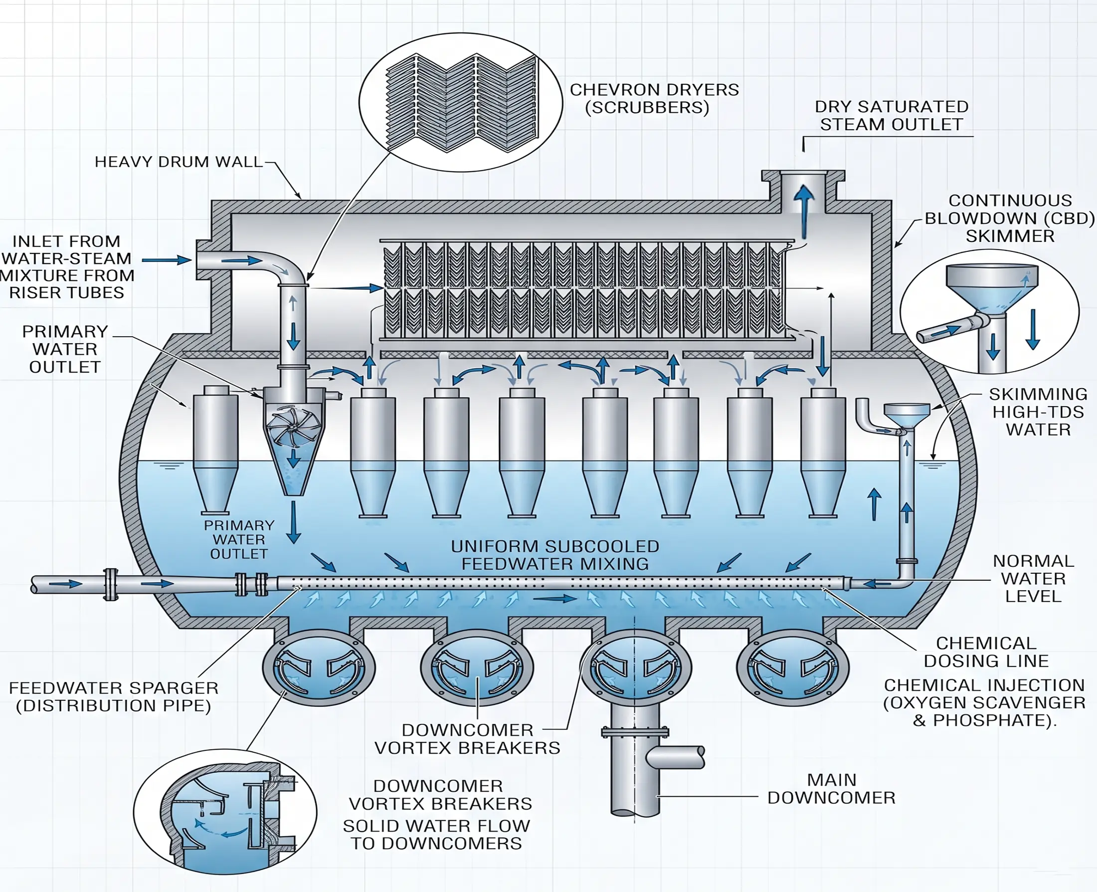
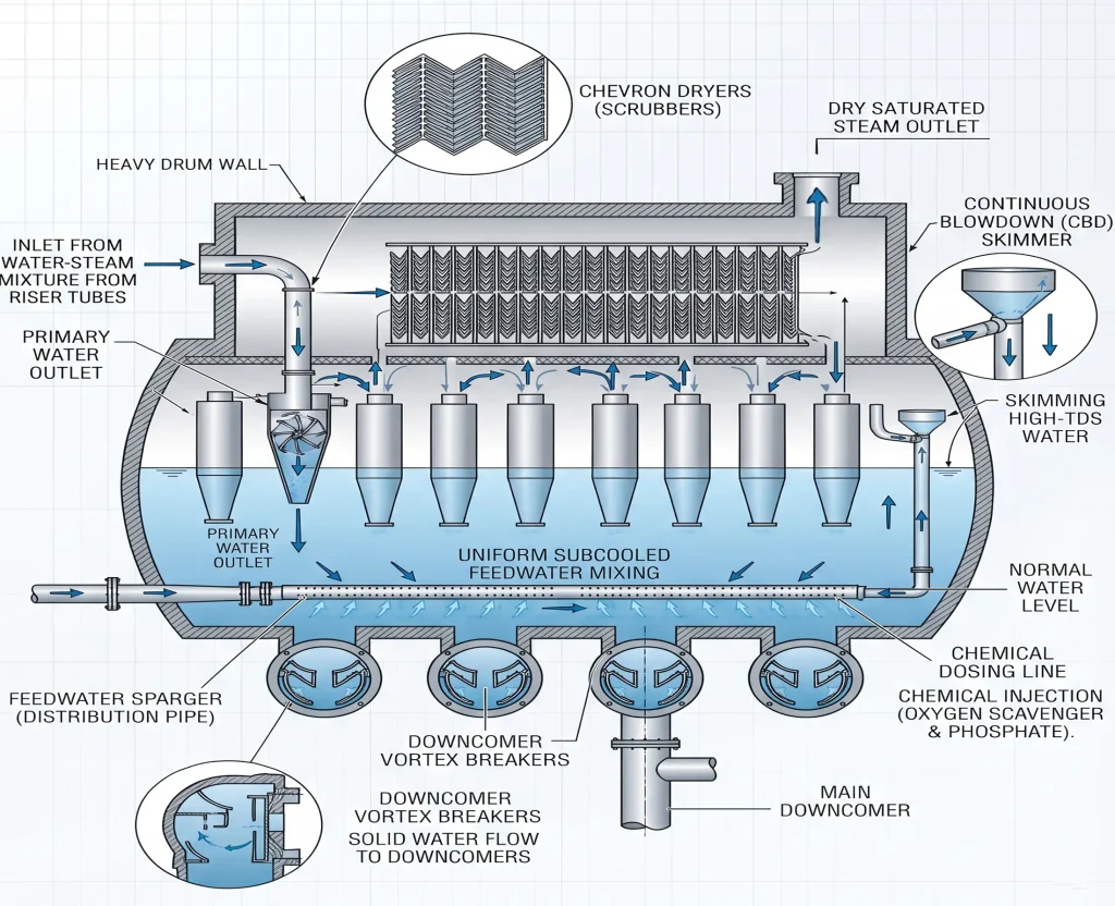
The boiler steam drum is one of the most important components of the water tube boiler. The boiler steam drum holds the water and also provides the space which is required for the separated steam from the steam-water mixture which is generated inside the evaporator tubes of the boiler.
Table of Contents
What is a boiler steam drum?
A boiler steam drum is a horizontal cylindrical pressure vessel 10 to 180 bar which is installed at the upper portion of a drum-type water-tube boiler. It receives the steam-water mixture from the evaporator tubes or the water wall tubes and separates the generated steam from the liquid water. The separated water gets recirculated via the downcomers while the separated steam flows towards the Superheater.
Functions of a boiler steam drum
The boiler steam drum performs several important functions. These functions are listed below.
Steam-water separation
The boiler steam drum receives the steam-water mixture from the evaporator tubes. It separates the steam from the liquid water by the use of an internal separator, which uses gravity as well as centrifugal action to drive out the denser water droplets, and the steam being lighter, rises above.
The steam then passes through chevron dryers or scrubbers, which capture and drain the residual microdroplets. This ensures that the steam leaving the boiler steam drum is in a dry condition.
Water reserve
The boiler steam drum maintains a stable water reserve to feed the downcomers. Thus, it also absorbs the fluctuation caused by the load transient, preventing the boiler tube from starvation during sudden steam-demand spikes.
Feed water inlet and distribution
The boiler steam drum receives the incoming feedwater via the boiler feed pump. The incoming water is relatively cool, in the range of 100 to 110°C, from the deaerator. This incoming feedwater is distributed in the steam drum through a perforated feed pipe, which runs axially along the bottom of the drum, distributing the flow evenly along the drum length and directing it into the water space below (rather than creating a cooler environment in the steam separation zone).
This type of distribution, which is adopted in most boiler steam drum designs, prevents causing of a thermal shock to the boiler steam drum shell or the formation of any cooling zone (which would disturb the density or natural water circulation).
Chemical treatment
The boiler steam drum is the primary interface for the chemical treatment of the internal circulating boiler water. In the steam drum high-pressure chemical dosing is done by a high-pressure positive displacement metering pump to overcome the operating pressure. The essential internal water treatment includes oxygen scavengers (hydrazine or carbohydrazide), scale/phosphate inhibitors, pH adjusters (ammonia or amines), and anti-foaming agents. These chemicals, mixes in the boiler steam drum thoroughly before being distributed in the evaporator tube circuit. Additionally the boiler steam drum also features a continuous blowdown connection, or CBD, which systematically removes the concentrated dissolved solids and prevents scale deposition.
Internal components of Boiler Steam Drum
Cyclone Separators
The primary separators remove most of the liquid water particles from the incoming steam and water mixture from the risers. Depending on the design of the boiler, the primary steam separator can include cyclone separators or separation devices. The cyclone separator uses centrifugal action to drive the denser water particles to the outer walls, draining to the water space below. The steam, being lighter, exits upward from the center of the cyclone separator towards the secondary separation zone.
The steam from the cyclone separator still contains some fine water droplets and these droplets rise high in steam space of the drum. The steam space of the drum is the distance or the gap from the water surface below to the top of the drum. The size of the steam space determines the gravitational settling, or the secondary separation. The larger the steam space is, the better the quality of secondary steam separation as it provides more gravitational settling distance.
Chevron Dryer
These are the dryers, which are positioned above the cyclone separator and consist of metallic parallel alternate ridges or grooves through which the steam takes a path full of twists and turns. The inertial impaction thus causes the microdroplets, present in the steam to coalesce into films, which drains back down to the water space below, ensuring a dry steam that exits to the superheater.
Downcomer inlet baffles
The downcomer inlet baffles are installed at the entrance of the downcomer pipes at the bottom of the boiler steam drum. It prevents the formation of suction vortices, which ensures that only bubble-free water enters the downcomer to feed the furnace wall radiant circuit.
Riser baffles or splash plates
These are installed in the riser or evaporator tubes, in the entry of the boiler steam. The splash plate absorbs the kinetic energy of the high-velocity steam-water mixture and distributes it evenly toward the primary separators.
The operating cycle of the boiler steam drum
During cold startup and run preservation, the feedwater fills the system via the inlet of the cylinder, distributing the feedwater downwards via the downcomers to the bottom header or the macro, and to the radiant evaporator tube bank.
As the burner fires and the flue gases heat the water tubes, boiling of the water begins. The pressure inside the steam drum begins to develop as steam accumulates in the upper drum (steam space). During this phase the main steam outlet valve remains closed until the rated pressure is achieved.
The formation of steam in the evaporator tubes sets up a density difference between the riser tubes and the downcomer tubes, which establishes a natural thermal circulation. This circulation is self-regulating as higher heat input generates more steam, which reduces the water density further and accelerates the upward flow. This draws the cool water from the lower drum faster, automatically matching the circulation rate to the thermal load.
The two-phase steam-water mixture enters from the riser tube and passes through the drum’s internal steam separation hardware, like the cyclone separators, the gravitational settling zone, and the chevron or demister dryers, which de-moisturize the steam and drains the water particles to the bottom of the drum.
The dry steam accumulates in the upper drum space and exits the boiler steam drum through the main steam outlet nozzle at the desired pressure and dryness fraction, ready for superheating.
As the water converts to steam and exits the drum, the water level in the drum naturally depletes. To maintain the water level, the modern high-capacity boilers utilize a three-element control system, which are monitors the drum level, steam flow, and feed water flow to continuously modulate the feedwater regulator valves.
However the water level of the boiler steam drum is the primary real-time indicator of the system’s mass balance.
The continuous blowdown from the steam drum’s water surface removes the highly concentrated dissolved solids while the intermittent bottom blowdown removes the settled sludge from the lower header or the mud drum.
High-pressure positive displacement metering pumps inject the chemical dosing directly in the boiler steam drum, ensuring mixing and distribution through the entire evaporator circuit to prevent corrosion and scaling.
Classification of boiler steam drum as per configuration and layout
Geometry of the boiler dictates how many drums are needed to be integrated in the primary pressure circuit of the boiler.
Single drum configuration
It features one primary steam drum located at the top of the boiler circuit. It is a standard configuration in modern D-type, O-type, and high-capacity utility water-tube boilers. All the risers enter the single vessel, optimizing the structural overhead with three-element level control.
Bi-Drum our two-drum configuration
These usually has two drums, the upper is the steam drum and at the bottom sits the mud drum. Both of the drums are connected by an extensive bank of the generating tubes. This type of design is extensively used in industrial solid fuel, biomass, and gas-fired units. The lower drum acts as a collection header for suspended sludge.
Tri-drum or multi-drum configuration
This design utilizes three interconnected drums. The upper steam drum with two lower water drums, common in older A-type designs, specialized for low-profile industrial layouts. This design maximizes the convective heating surface and the steam disengagement area.
Classification based on manufacturing method
Fusion welded plate drums
These are constructed from heavy-walled carbon or alloy steel plates rolled into semicylindrical halves, joined by longitudinal and circumferential fusion-welded seams, and sealed with hemispherical or elliptical dished ends. These boiler steam drums are standard for medium- to high-capacity utility and industrial power boilers.
Seamless forged drums
This type of drum is machined and forged out of a single solid ingot or pierced billet without any welded seams. This valve design is utilized for ultra-high-pressure or severe-duty subcritical applications. Absence of welded seams removes the stress concentration points and metallurgical vulnerabilities under cyclic fatigue.
Material classification of boiler steam drums
Carbon manganese steel
SA-516 Grade 70 or SA-299 equivalent plates are utilized for standard subcritical boiler steam drums operating at 120 to 150 bar and moderate temperature below 350°C.
Molybdenum and chromium-molybdenum alloy steels
SA-336 first alloy grade or SA-387 specifications are used in utility subcritical boilers operating between 150 and 180 bar and saturation temperature approaching 365°C where higher tensile strength and creep resistance are required under these elevated temperature and pressure situations.
Reference
ASME Boiler and pressure vessel codes
This article is a part of thermal system, where other related articles are discussed.