
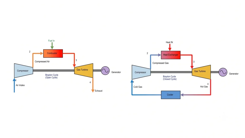
Brayton cycle is an ideal thermodynamic cycle that forms the principle of operation of gas turbines used in aircraft propulsion and power generation. Brayton cycle was proposed by George Brayton in the 19th century as the cycle consists of two isentropic processes and two constant-pressure processes. Brayton cycle also serves as the theoretical foundation for modern gas turbine power plants and combined cycle power plants (CCPPs).
Unlike Rankine cycle, which uses water as the working fluid, the Brayton cycle typically uses air and combustible gases. Air is firstly compressed and mixed with fuel in a combustion chamber where heat is added to it at constant pressure, it is then expanded through a turbine to produce the work, and finally exhausted in to the atmosphere (open cycle) or the working fluid is cooled via heat exchanger or cooler before it enters the compressor again in a closed cycle.
Table of Contents
Working Principle of the Brayton Cycle
The Brayton cycle operates on four basic components, these are:
Compressor: Compresses the working fluid.
Combustion chamber (or external heater in a closed cycle): Adds heat to the working fluid at constant temperature.
Turbine: The working fluid expands here and produces work.
Heat rejection system or exhaust: Either the gas is rejected to the atmosphere (open system) or is cooled in an heat exchanger for further compression in the compressor (closed system).
The working fluid first enters the compressor, where its pressure and temperature increase due to the process of isentropic compression. The compressed air then flows into the combustion chamber, where fuel is burned and heat is added at nearly constant pressure.
The high-temperature, high-pressure gases expand through the turbine, producing useful work. A portion of this work is used to drive the compressor, while the remaining work is available for electricity generation or propulsion.
Finally, the exhaust gases leave the turbine and reject heat to the surroundings (open cycle) or are cooled before entering the compressor again (closed cycle).
It shall be noted that in a closed Brayton cycle, the working fluid does not comes in direct contact with the combustion gas.
Processes of the Ideal Brayton Cycle
The ideal Brayton cycle consists of four internally reversible processes.
Process 1–2: Isentropic Compression
Air enters the compressor at low pressure and is compressed reversibly without heat transfer.
Since the process is isentropic,
As compressor requires work input, therefore,
For an ideal gas,
where
- P2/P1= pressure ratio (rp)
- γ = Cp/Cv
During compression, the pressure of the working fluid increases, temperature increases while the specific volume decreases and the entropy remains constant.
Process 2–3: Constant-Pressure Heat Addition
As the compressed air enters the combustion chamber, where fuel is injected and burned.
The combustion process occurs approximately at constant pressure.
Therefore,
The heat supplied in this process is
During this process, the temperature of the working fluid increases significantly along with the enthalpy, while the specific volume increases and pressure remain nearly constant as the flow is not restricted.
The maximum cycle temperature is reached at the end of this process and is known as the turbine inlet temperature. It is one of the most important parameters affecting Brayton cycle performance.
Process 3–4: Isentropic Expansion
The high-temperature gases expand through the turbine and produces the work.
Since the turbine process is ideally reversible and adiabatic,
Therefore, the turbine work is
The temperature-pressure relation is
During the turbine expansion process, the pressure decreases along with the temperature, while the specific volume increases and the entropy remain constant.
The gas turbine generates more work than the compressor consumes, and the difference is the net work output of the cycle.
Process 4–1: Constant-Pressure Heat Rejection
In this process, the working fluid rejects heat to the surroundings while maintaining nearly constant pressure.
For an open-cycle gas turbine, this process corresponds to the exhaust gases leaving the turbine.
For a closed Brayton cycle, the working fluid passes through a cooler before entering the compressor again.
Therefore, the heat rejected is
Where,
The cycle is then keeps repeating continuously producing work.
P–V and T–S Diagrams
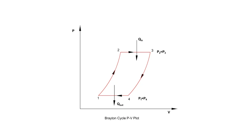
The P–V diagram of the Brayton cycle consists of two isentropic curves connected by two constant-pressure lines. The area enclosed by the cycle represents the net work produced.
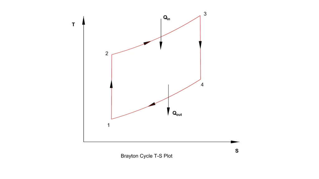
The T–S diagram is more useful for understanding heat transfer. The vertical lines represent the isentropic compression and expansion processes because entropy remains constant. The constant-pressure heat addition and heat rejection processes appear as inclined curves. The area enclosed by the T–S diagram is proportional to the net heat transfer during the cycle.
Thermal Efficiency of the Brayton Cycle
The thermal efficiency of a heat engine is defined as the ratio of net work output to the heat supplied.
Since,
the thermal efficiency becomes
For the ideal Brayton cycle,
and
Substituting these expressions,
Cancelling mCp,
For the Isentropic compression process (1→2),
where
Therefore,
Rearranging,
Also from ideal gas equation,
We get,
Rewriting it and substituting the value of V2/V1
Or,
Since, the pressure ratio is
Therefore,
Or,
Similarly for the adiabatic expansion process in turbine (3→4),
Or,
Now,
Substituting the value of (T3-T2) in the efficiency equation
We get
where
- rp = P2/P1 =P3/P4 is the pressure ratio.
- γ = Cp/Cv is the ratio of specific heat.
This equation shows that the thermal efficiency of an ideal Brayton cycle depends primarily on the pressure ratio. As the pressure ratio increases, the cycle efficiency also increases. However, in practical gas turbines, beyond 20:1 pressure ratio reduces the net work output because the compressor then draws disproportionately more power.
Cycle Improvements
Several modifications are employed in modern gas turbines to improve the performance of the Brayton cycle. Among them are:
Regeneration
In the simple Brayton cycle, the exhaust gases leaving the turbine still possess a considerable amount of thermal energy amounting to around 30% of the fuel’s energy with temperatures upto 600 °C. Instead of releasing this energy to the atmosphere, a regenerator (heat exchanger) is installed in the exhaust pathway, whichtransfers part of the exhaust heat to the compressed air before it enters the combustion chamber.
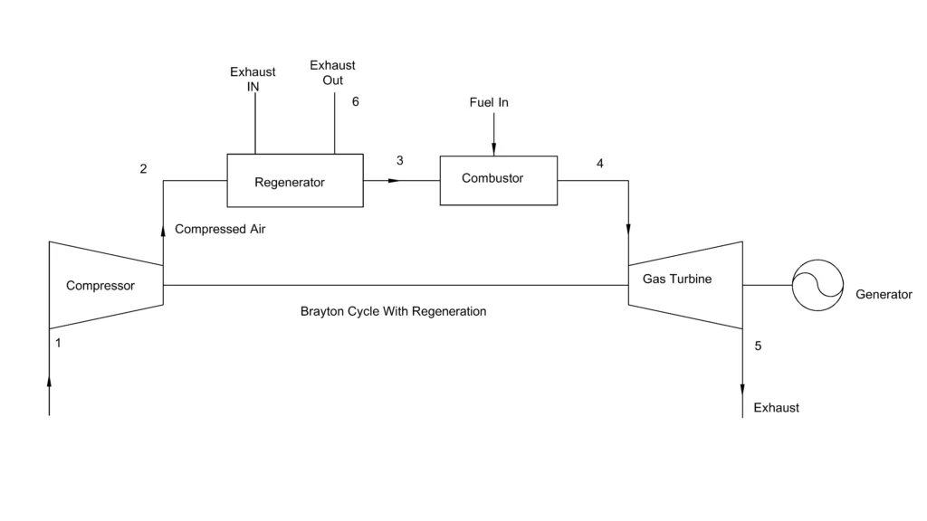
This modification results in lowering the fuel requirement to achieve the desired turbine inlet temperature, thus improving the cycle’s thermal efficiency.
It can be noted that regeneration is only effective when the turbine exhaust temperature is higher than the compressor outlet temperature. In high pressure ratio gas turbines, the compressor outlet temperature approaches the exhaust gas temperature and the benefit of regeneration diminishes. Regeneration is widely used in stationary gas turbine power plants where efficiency is more important than the compact size.
Intercooling
Intercooling greatly reduces the work requirement during compression process.
The compression of air is divided into two or more stages and between the stages, the compressed air is made to pass through an intercooler where it is cooled before entering the next stage of compression.
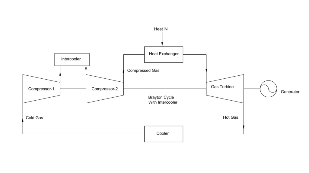
The intercooler lowers the compression work, increases the specific work output while lowering the compressor outlet temperature.
Although intercooling increases the net work output, but it also lowers the air temperature entering the combustion chamber. Therefore, when intercooler is solely used, it can reduce thermal efficiency as more fuel will be needed to reach the turbine inlet temperature. Intercooling is often combined with regeneration to improve both the work output and efficiency.
Reheating
Reheating increases the work produced by the gas turbine.
Instead of expanding the working fluid of the Brayton cycle through a single gas turbine stage, the expansion is divided into two stages. After partial expansion, the gas is reheated again at constant pressure in a second combustion chamber before entering the next turbine stage.
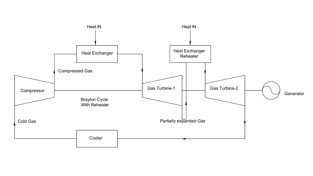
The advantages of reheating includes higher turbine work with increased specific power output.
However, reheating alone generally decreases thermal efficiency because additional fuel is required during the second heating process. It is though preferred where high power output is important than the thermal efficiency. When reheating is combined with regeneration and intercooling, it significantly improves the overall cycle performance.
Applications of the Brayton Cycle
The Brayton cycle forms the basis of many modern thermal systems.
Major applications include:
- Aircraft turbojet and turbofan engines.
- Industrial gas turbine power plants.
- Combined cycle power plants (CCPPs).
- Marine propulsion systems.
- Oil and gas processing facilities.
- Small distributed power generation units.
Because of the ability to produce large amounts of power with compact equipment size, the Brayton cycle remains one of the most important thermodynamic cycles in mechanical and power engineering.
Reference
- NASA Glenn Research Center – Turbine Engine Thermodynamic Cycle – Brayton Cycle
- Moran & Shapiro – Fundamentals of Engineering Thermodynamics
- U.S. Department of Energy – How Gas Turbine Power Plants Work
This article is a part of thermal system, where other related articles are discussed.