
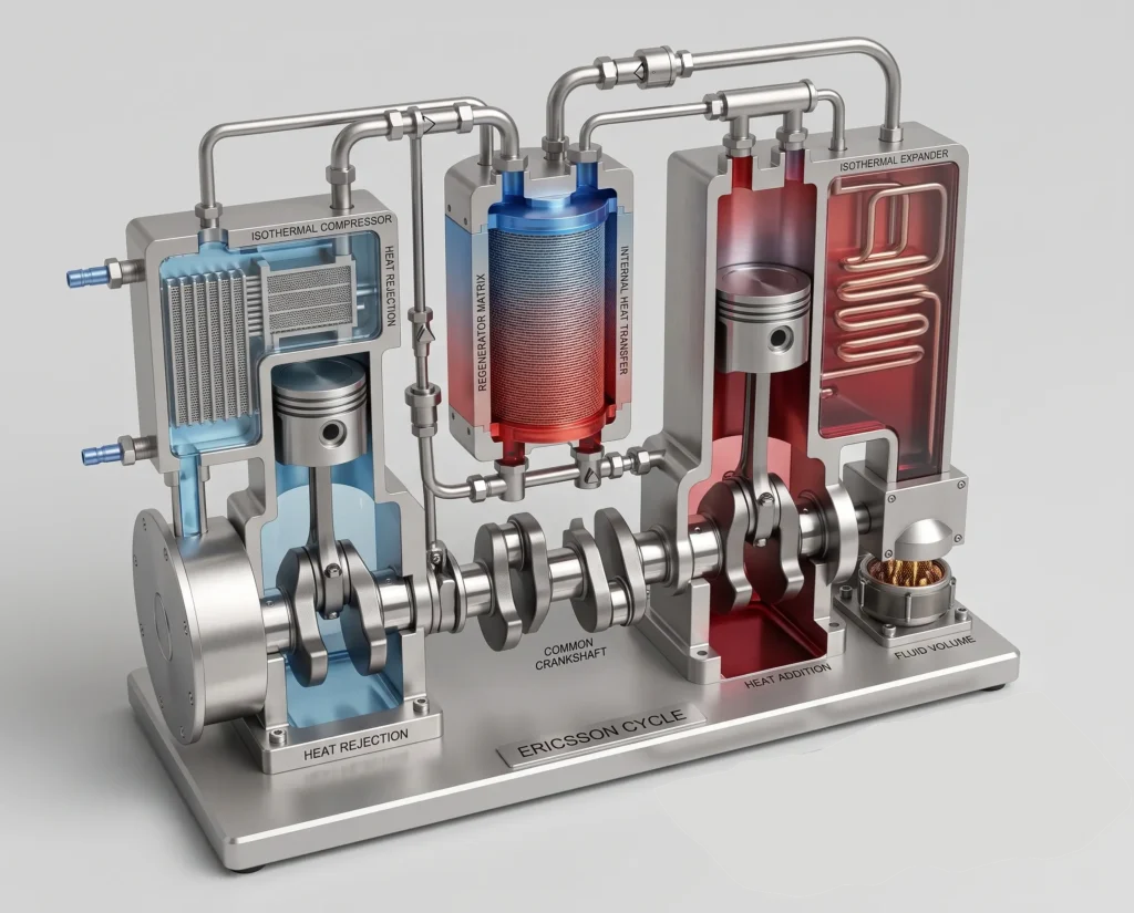
The Ericsson cycle is an ideal regenerative thermodynamic cycle having two isothermal processes and two constant-pressure regenerative processes. Like the Stirling cycle, the Ericsson cycle also uses regeneration to recover heat within the cycle.
The ideal Ericsson cycle is considered important in thermodynamics as it achieves the same maximum theoretical efficiency as that of a Carnot cycle, operating between the same high and low temperature limits.
The major difference between the Ericsson and Stirling cycles is the nature of the regenerative processes. The Stirling cycle uses constant-volume regeneration, whereas the Ericsson cycle uses constant-pressure regeneration.
Table of Contents
What Is the Ericsson Cycle?
The Ericsson cycle is a regenerative thermodynamic cycle that operates between a high-temperature reservoir at TH and a low-temperature reservoir at TL with a working fluid, which is typically considered to be an ideal gas.
Ericsson cycle usually has a regenerator, which stores the heat from the working fluid during the cooling process and then supplies the stored thermal energy to the working fluid during the heating process of the next cycle. Thus, the regenerator saves the heat requirement of the cycle and with perfect regeneration and reversible heat transfer, the Ericsson Cycle attains the Carnot efficiency.
How Does the Ericsson Cycle Work?
The Ericsson cycle can be understood as a sequence of compression, regeneration, expansion, and regeneration processes.
During the low-temperature isothermal compression process, work is supplied to compress the working gas. The gas rejects the heat to the low-temperature reservoir while keeping its temperature constant.
After the isothermal compression, the gas is then heated at constant pressure. Ideally, this heat is supplied by the regenerator.
The working gas then undergoes isothermal expansion at the high temperature. During this process, heat is supplied from the high-temperature source and the expansion of the gas produces the work.
Finally, the gas is cooled at constant pressure, where the regenerator receives the heat from the gas and stores it for use in the next cycle.
Thus the cycle returns to its initial state.
The Four Processes of the Ericsson Cycle
Process 1–2: Isothermal Compression
During this process, the working gas is compressed at the lower temperature TL.
Therefore,
Work is supplied to the gas during this process of compression. For an ideal gas, the work during an isothermal process is:
Since,
the value of work done W12 is negative as when work is done by the system is considered positive as convention.
In this process, the gas rejects heat to the low-temperature reservoir. Therefore, for a reversible isothermal process
using the convention that heat and work supplied by the system are positive.
The noticeable feature of this process is that the working gas is compressed while remaining at the lower temperature.
Process 2–3: Constant-Pressure Regenerative Heating
The working gas is then heated at constant pressure. Therefore,
The temperature increases from
Since the pressure remains constant, the volume of the gas increases according to the ideal-gas relation.
At constant pressure,
Therefore, as the temperature increases, the volume also increases. Ideally, the required heat during this process is supplied by the regenerator.
For a constant-pressure process,
Therefore, the regenerator must have previously stored approximately this amount of thermal energy during the constant-pressure cooling process.
Process 3–4: Isothermal Expansion
In this process, the working gas expands at a constant high temperature TH.
Therefore,
And heat is supplied to the gas from the high-temperature reservoir. Thus, the gas expands and produces work.
Because,
the work produced during this process is positive.
This process is the primary work-producing process of the Ericsson cycle. The gas absorbs heat while expanding at constant temperature.
For a reversible isothermal process,
Process 4–1: Constant-Pressure Regenerative Cooling
During this final process, the gas is cooled at constant pressure. Therefore,
The temperature decreases from
As the pressure remains constant during the process, the volume decreases. The heat rejected by the gas is transferred to the regenerator and it stores the heat.
For an ideal gas,
The regenerator stores this heat and returns the same to the working gas during Process 2–3.
In the ideal case,
Thus, the regenerative heat is internally recovered in the cycle rather than being supplied continuously by an external heat source.
Ericsson Cycle PV Diagram
The pressure-volume diagram of the ideal Ericsson cycle contains the following
- Two isothermal curves
- Two constant-pressure processes
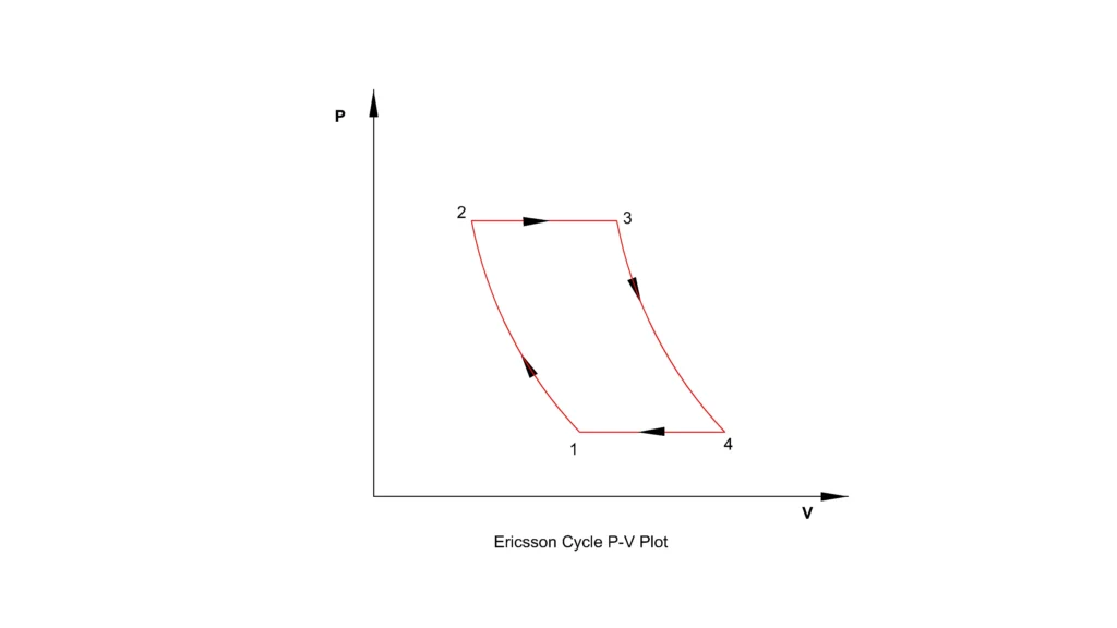
The isothermal compression occurs at the lower temperature TL. While the isothermal expansion occurs at a higher temperature TH.
The two regenerative processes occurs at constant pressure. The enclosed area on the PV diagram represents the net work produced by the cycle.
Ericsson Cycle T–S Diagram
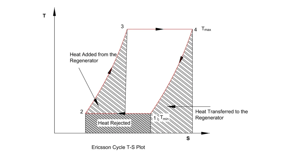
The temperature-entropy or TS diagram provides a useful way to understand the heat-transfer processes.
The Ericsson cycle contains
- Isothermal compression at TL
- Constant-pressure regenerative heating
- Isothermal expansion at TH
- Constant-pressure regenerative cooling
For a reversible process
Therefore, the area under a process on the TS diagram represents heat transfer.
The two isothermal processes occur as horizontal lines on the TS diagram as the temperature remains constant. The regenerative processes connects the high and low temperatures while heat is internally transferred through the regenerator.
In the ideal Ericsson cycle, the regenerative processes are reversible and the regenerator operates with 100% effectiveness.
Ericsson Cycle Efficiency
The ideal Ericsson cycle achieves the Carnot efficiency when regeneration is perfect.
The thermal efficiency of Ericsson cycle is
The heat input or supplied is from the process 3-4 isothermal expansion
The heat is rejected during the process of isothermal compression 1-2. Therefore, the magnitude of the heat rejected is
For process 2-3, the pressure is constant, P2=P3
Using ideal gas equation, PV=nRT we get,
Similarly for process 4-1, P4=P1, using the ideal gas equation we get,
Rearranging both we get,
Therefore their logarithmic volume ratio will also be equal
Substituting the above values in the efficiency equation
This is the ideal thermal efficiency.
However, a practical Ericsson-cycle engine would achieve a lower efficiency because of irreversibilities and imperfect regeneration.
Why Does the Ericsson Cycle Achieve Carnot Efficiency?
The ideal Ericsson cycle achieves Carnot efficiency because it combines:
- Reversible isothermal heat addition
- Reversible isothermal heat rejection
- Perfect regeneration
The regenerative processes do not require any external heat transfer in the ideal case. Thus, the external heat supplied to the cycle is therefore associated with the high-temperature isothermal expansion only.
The Role of the Regenerator
The regenerator is the most important component of the Ericsson cycle that separates it from simple heat engine cycles.
During the constant-pressure cooling process, the working gas transfers heat to the regenerator.
During the constant-pressure heating process of the next part of the cycle, the regenerator returns this heat to the working gas.
Therefore, the external heat source does not need to supply all the heat required to raise the working gas from TL to TH.
A practical regenerator, however, has finite effectiveness and not 100%.
The performance of the regenerator is affected by the following
- Heat-transfer surface area
- Thermal conductivity
- Heat capacity
- Temperature gradient
- Gas velocity
- Pressure drop
- Thermal conduction between hot and cold sides
If the regenerator is ineffective, the external heat supply increases and consequently the thermal efficiency of the cycle decreases.
Ericsson Cycle Equations
Several equations are useful for analysing the ideal Ericsson cycle.
Isothermal Work
For an ideal gas undergoing an isothermal process,
For isothermal expansion,
For isothermal compression,
Constant-Pressure Heat Transfer
For an ideal gas heated at constant pressure,
Therefore, during regenerative heating,
During regenerative cooling,
The heat rejected during cooling is ideally stored in the regenerator.
Net Work
For a complete cycle,
The exact net-work calculation depends on the selected sign convention and the heat and work interactions assigned to each process.
Ericsson Cycle vs Stirling Cycle
The Ericsson and Stirling cycles are closely related regenerative cycles.
Both contains the following:
- Two isothermal processes
- Two regenerative processes
- A regenerator
- Theoretical Carnot efficiency under ideal reversible conditions
The major difference is the nature of the regenerative processes.
| Feature | Ericsson Cycle | Stirling Cycle |
| Isothermal processes | 2 | 2 |
| Regenerative processes | Constant pressure | Constant volume |
| Regenerator | Required | Required |
| Ideal efficiency | Carnot efficiency | Carnot efficiency |
| Working fluid | Typically an ideal gas | Typically a gas |
| Practical implementation | Difficult | More practical |
In the Ericsson cycle, the gas is heated and cooled at constant pressure during regeneration. While, in the Stirling cycle, the gas is heated and cooled at constant volume.
This difference produces different mechanical implementation requirements.
Advantages of the Ericsson Cycle
High Theoretical Efficiency
The ideal Ericsson cycle can achieve Carnot efficiency between the same temperature limits.
Regenerative Heat Recovery
The regenerator recovers heat that would otherwise be rejected from the cycle.
External Heat Addition
The cycle can theoretically operate using an external heat source. Potential heat sources include:
- Solar energy
- Waste heat
- Biomass
- Nuclear heat
- External combustion
Flexible Heat Sources
Since, the heat is supplied externally, the cycle is not restricted to a particular process of combustion.
Limitations of the Ericsson Cycle
Perfect Isothermal Heat Transfer Is Difficult
The cycle requires heat addition and rejection at constant temperature. But real heat exchangers require a finite temperature difference to transfer heat. This creates an irreversibility.
Regenerator Effectiveness Is Limited
A real regenerator cannot recover all the heat stored during the cooling process. This means a drop in effectiveness, which results in additional external heat requirement and reduction in thermal efficiency.
Pressure Drop
The working gas must flow through heat exchangers at source and sink and also through the regenerative equipment. Pressure losses thus increase the required compression work and reduce the net power output.
Heat Exchanger Size
High heat-transfer rates require sufficient heat-transfer surface area. This increases the size, weight, and cost of the system.
Applications of the Ericsson Cycle
The ideal Ericsson cycle is primarily studied as a theoretical regenerative thermodynamic cycle. However, the principles are relevant to several advanced thermal systems.
The direct commercial use of the Ericsson cycle is limited because achieving the isothermal and regenerative processes is technically very challenging.
Ericsson Cycle: Ideal vs Real Performance
The ideal Ericsson cycle assumes the following
- Reversible compression
- Reversible expansion
- Perfect regeneration
- Isothermal heat addition
- Isothermal heat rejection
- No pressure losses
- No mechanical friction
- No heat leakage
But the real systems deviate from these assumptions.
The actual efficiency is reduced by:
The major sources contributing to the entropy generation includes
- Heat transfer across finite temperature gradient
- Pressure losses
- Mechanical friction
- Imperfect regeneration
- Heat leakage
- Gas-flow losses
Therefore, although the ideal Ericsson cycle has Carnot efficiency, a practical system will always perform below the ideal value.
Reference
- Ericsson Cycle – Theory and Efficiency
- Substance Independence of Efficiency of a Class of Heat Engines Undergoing Two Isothermal Processes
- Thermo-Environmental Analysis and Multi-Objective Optimization of Performance of Ericsson Engine
This article is a part of thermal system, where other related articles are discussed.