
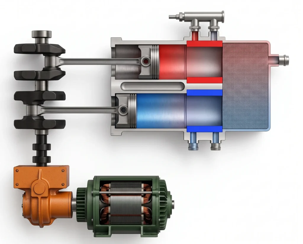
Stirling cycle is a regenerative, closed thermodynamic cycle that operates with a heat source which is external. Unlike other thermodynamic cycles like Rankine cycle or Carnot cycle, where the heat is directly added inside the working system, in the Stirling cycle, heat is added through external heat exchanger. This allows the Stirling cycle to use different heat sources like solar energy, waste heat, biomass and other thermal sources.
Table of Contents
What is Stirling cycle?
The Stirling cycle is a closed thermodynamic cycle consisting two isothermal and two constant volume regenerative processes. The cycle uses a permanently enclosed working gas, such as helium, hydrogen or air. This gas circulates between a high temperature region and a low temperature region while its pressure and temperature changes.
The distinguishable feature of the Stirling cycle is the regenerator. It stores thermal energy from the working gas during one part of the cycle and releases the stored heat to the gas during the other part of the cycle. By doing so, the regenerator reduces the amount of external heat requirement and helps achieve a high theoretical efficiency for an ideal Striling cycle.
How does the Stirling cycle work?
A practical heat engine working on Stirling cycle contains a hot region and a cold region, a regenerator and a working gas enclosed in the engine.
The enclosed working gas moves between the hot and the cold region, while a displacer or piston arrangement controls the volume of the gas and its position relative to the heat source and sink.
When the gas moves to the hot region, its temperature and pressure increases. When it moves to the cold region, the heat is rejected and the gas contracts. The engine produces the net work output because the gas expands at a high temperature compared to the temperature at which it is compressed. This is the fundamental principle behind this cycle.
Cyclical expansion occurs at a high temperature and compression occurring at a low temperature.
The Four processes of the Stirling cycle
An ideal Stirling cycle consists of two isothermal and two constant volume processes.
Process1-2: Isothermal Compression
During this process, the working gas is compressed at a constant low temperature TL. As the compression work is supplied to the gas, there is a tendency of temperature rise in the gas. In order to maintain constant temperature, heat is rejected to the low temperature reservoir or sink.
For an ideal gas, T = TL and
The work during the isothermal compression is
Since, V2 < V1 the work is negative.
The convention is that when the work is done by the system, it is positive and when the work is done on the system, its negative.
Process 2-3: Constant Volume Regenerative Heating
After completion of the isothermal compression process, the gas is heated at constant volume. Therefore,
V2 = V3
During this process, the working gas passes through the regenerator and absorbs the heat stored in it during the previous half of the cycle. Since, the volume remains constant, the work done in this process is zero.
W2-3 = 0
The temperature of the gas increases from TL to TH
For an ideal gas, the pressure increases as the volume remains constant while the temperature increases.
The heat required for this process is ideally supplied by the regenerator rather than directly by the external heat source.
Process 3-4: Isothermal Expansion
At this stage, the gas expands at constant temperature TH and during this expansion, the gas produces the work.
T = TH = Constant
The heat supplied to the gas is converted to expansion work, while the temperature remains constant.
The work done during this process
Since, V4 > V3 , the gas performs the positive work. This is the main process of the Stirling cycle, which produces the work.
Process 4-1: Constant Volume Regenerative Cooling
The final process of the Stirling cycle occurs at a constant volume.
V4 = V1
The working gas passes through the regenerator and transfers the heat back to it. The temperature of the gas decreases from TH to TL.
And since the volume remains constant, Work done during this process is zero.
W4-1 = 0
The regenerator stores the heat and returns back to the working gas during process 2-3 of the next cycle.
After completion of this process, the cycle returns to its initial state.
Stirling Cycle PV and TS Diagrams
The pressure-volume diagram of the ideal Stirling cycle contains two isothermal curves and two constant volume lines.
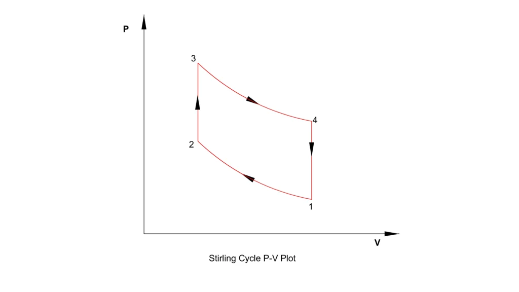
The isothermal expansion occurs at the higher temperature TH, while the isothermal compression occurs at lower temperature TL.
The area enclosed by the cycle on the PV diagram represents the network produced by the cycle.
WNet = W1-2 + W3-4
Since, the two constant volume process involves no boundary work,
W2-3 = W4-1 = 0
The TS diagram represents the temperature and entropy changes during each process.
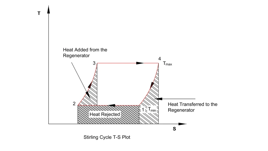
During the two-isothermal process, temperature remains constant while the entropy changes. During the regenerative processes, the temperature changes, while heat is stored in or recovered from the regenerator.
For the reversible process
δQ = TdS
where δQ is the change in heat, dS is the change in entropy and T is the temperature.
Therefore, the area under a process on the TS diagram represents the heat transfer associated with that process.
Stirling Cycle Efficiency
The ideal Stirling cycle has the same efficiency as that of a Carnot Cycle operating between same maximum and minimum temperatures.
The ideal thermal efficiency is
where,
TH is the temperature of the source (High temperature reservoir) in kelvin.
TL is the temperature of the sink (Low temperature reservoir) in kelvin.
For example, if a Stirling engine works between 800K and 300K as temperature of heat source and heat sink, then
=0.625 = 62.5%.
This is an ideal value. However, real Stirling engine would achieve a lower efficiency.
Why is Stirling Cycle Theoretically So Efficient?
The ideal Stirling cycle achieves Carnot Cycle level efficiency because the heat addition and heat rejection occurs isothermally, while the intermediate heating and cooling processes are performed through perfect regeneration.
The ideal Stirling cycle includes the following assumptions:
- The regeneration is perfect.
- The temperature difference during heat transfer is zero.
- There is no mechanical friction involved.
- There is no loss of pressure.
- The engine has no gas leakage.
- All the processes are perfectly reversible.
- The working gas is ideal gas.
These assumptions are difficult to achieve in a practical engine.
Why is the Regenerator Important?
The regenerator in the Stirling cycle is a thermal storage device located between the hot and the cold regions of the engine.
During the constant volume cooling process, the hot working gas transfers the heat to the regenerator. And during the constant volume heating process, the comparatively cooler working gas absorbs the stored heat from the regenerator.
Therefore, the external heat source only supplies the heat associated primarily with the isothermal expansion process.
In a real engine, the regenerator has an effectiveness of less than 100%. Some heat is lost because of:
- Finite heat transfer rates
- Temperature gradient
- Thermal conduction
- Pressure drop
- Incomplete heat recovery
The performance of a regenerator is among the major factors determining the efficiency of a practical Stirling engine as the heat supply from the external source increases with drop in the regenerator’s performance. This increase in the heat supplied, reduces the thermal efficiency of the actual Stirling cycle.
Stirling Cycle Equations
For an ideal gas undergoing the isothermal expansion and compression, the work done is given by
For the isothermal expansion process in the cycle
For isothermal compression process in the cycle
If the volume ratio is same for the expansion and the compression process, the net work done can be expressed by
The ideal efficiency of the cycle remains
Although the efficiency depends upon the temperature limit of the cycle, the volume ratio affects the magnitude of the work produced per cycle.
Stirling Cycle VS Carnot Cycle
| Parameter | Stirling Cycle | Carnot Cycle |
| Isothermal expansion | Yes | Yes |
| Isothermal compression | Yes | Yes |
| Constant-volume processes | Yes—heat addition and rejection | No |
| Adiabatic/isentropic processes | No | Yes |
| Regeneration | Essential for ideal operation and Carnot efficiency | Not required |
| Ideal efficiency | Equal to Carnot efficiency with perfect regeneration | Maximum theoretical efficiency between two temperature limits |
| Heat addition | Isothermal heat addition at (TH) | Isothermal heat addition at (TH) |
| Heat rejection | Isothermal heat rejection at (TL), assisted by regeneration | Isothermal heat rejection at (TL) |
| Heat transfer | Requires external heat transfer during isothermal processes | Requires ideal reversible heat transfer with reservoirs |
| Practical engine | More feasible, but difficult to achieve high power density | Highly idealized and difficult to implement |
| Main limitation | Slow external heat transfer and dead volume | Requires perfectly reversible processes and infinitesimal temperature differences |
Advantages of the Stirling Cycle
External Heat Supply
Stirling cycle can use several external heat sources
- Solar energy
- Biomass
- Waste heat
- Natural gas
- Nuclear heat
As the combustion process does not occurs inside the cylinder.
Low Noise and Vibration
Stirling engines are relatively silent as no combustion occurs inside the engine cylinder.
High Theoretical Efficiency
The ideal Stirling cycle with perfect regeneration and reversible operation has Carnot efficiency between the same temperature limits.
Fuel Flexibility
The Stirling engine can operate with different heat sources, making it suitable for applications where fuel flexibility is important.
Potential for Combined Heat and Power
The waste heat from the cooling system can potentially be recovered for heating or other useful purposes.
Limitations of the Stirling Cycle
Heat-Transfer Limitations
The engine must transfer heat through external heat exchangers. This limits the response rate of the engine to load fluctuations.
Regenerator Losses
A practical regenerator cannot recover all the heat stored during the previous process.
Pressure Losses
The working gas must flow through heat exchangers and the regenerator. These components create pressure losses that reduce net power output.
Sealing Problems
High-performance Stirling engines often use high-pressure gases such as helium or hydrogen. Preventing leakage from sealed working gas circuit is technically challenging.
Manufacturing Complexity
The heat exchangers, regenerator, high pressure seals, and moving components require precise design and manufacturing.
Application of Stirling Cycle
The Stirling cycle is suitable for application where external heat source and high efficiency are important. Common application includes
- Concentrated solar power systems.
- Waste heat recovery.
- Combined heat and power systems.
- Remote power generation.
- Low emission lower systems.
- Cryogenic cooling systems with reversed Stirling cycle.
Reference
- Stirling Cycle Machine Analysis — Ohio University
- Stirling Cycle Machine Analysis — Israel Urieli, Ohio University
- NASA Stirling Engine Design Manual
- Stirling Engine — Arizona State University Physics Instructional Resource Team
This article is a part of thermal system, where other related articles are discussed.