CIRCUIT BREAKER 101 Easy Explanation

Automatic Switch/Circuit Breaker

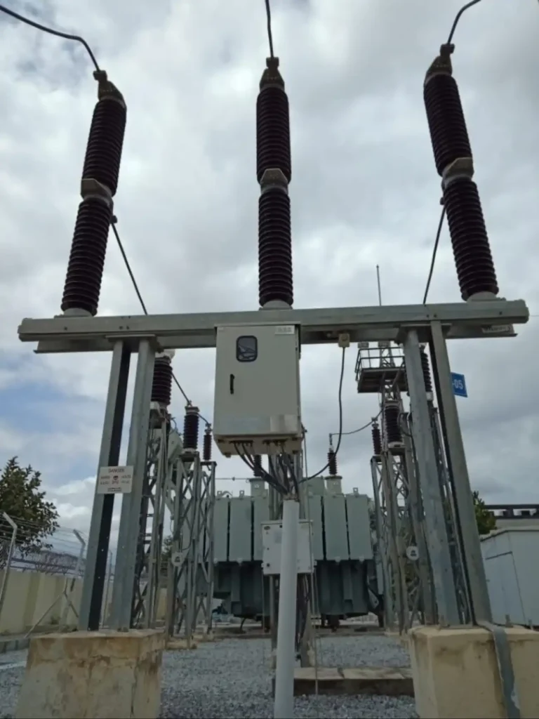
Circuit breaker

The Basic Principles of Circuit Breaker: –

The simplest circuit-interrupting device is the switch. By closing the switch against the action of a spring, we have an automatic device in which the energy for opening the contacts is stored by the closing operations.

Here only a small force and a short time are needed to open the switch by means of a simple latch which, when operated, releases the stored energy of the spring and opens the contacts. The switch now becomes a true circuit breaker, which can interrupt the current under predetermined conditions.

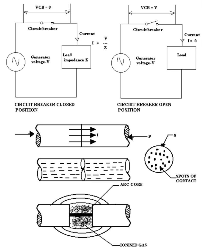
For example, when a short circuit occurs or when excess current endangers the system. This is obviously a very crude method of control and it is used only in low voltages. Hence, we can say that a circuit breaker is nothing but an automatic device for interrupting an electrical circuit whenever it is warranted by a fault condition. From the above explanation, it is understood that a circuit breaker has two working positions.

working of circuit breaker
  • A closed position is where the current flow is determined by the ratio of the applied voltage to the total impedance of the circuit.
  • An open position, where there is a zero current and the voltage of the source appears across the contacts of the circuit breaker.

The circuit breaker is designed to carry a rated current, which it must be able to carry continuously without its temperature rise exceeding the maximum specified permissible value for the rated voltage.  In order to consider the switching operation of a circuit breaker we must first understand the terminology used.

The switching operation is characterized by the value of the voltage and current before and after the action of the breaker. They are two values. (i) At the instant of contact closure the closing voltage, i.e. the rated voltage followed by the making current, and (ii) At the instant of contact separation, the breaking current followed by the recovery voltage. 

Making and breaking currents may differ considerably from the rated load current since their amplitudes will be several times larger. The recovery voltage name is derived from the fact, that at the incidence of a fault in the electrical system the voltage usually drops and after interruption of the circuit it gradually “recovers”. i.e. the initial voltage value after the interruption of the circuit is lower than that of the working voltage and then gradually attains its level.

The breaking capacity is usually expressed in Mega -Volt Amperes (MVA) and it is the product of the rated breaking current in kilo amperes and rated voltage expressed in kilo-volts. Hence breaking capacity for a three-phase circuit breaker whether symmetrical or asymmetrical,

                                                            = 1.732 X 3V X I X 10 -6 MVA

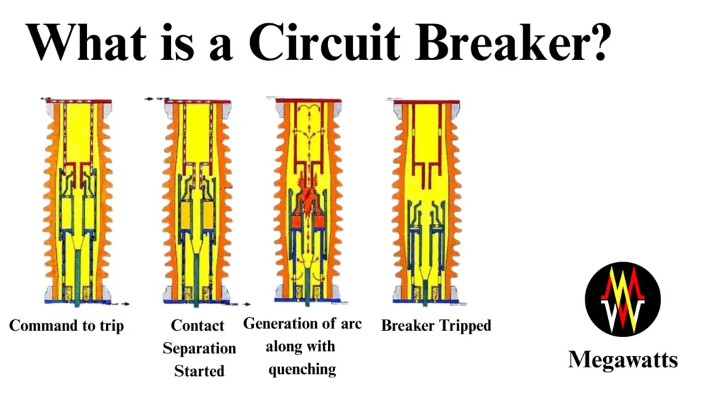
Before we proceed further, we shall see what happens when the circuit breaker is opened. As long as the contacts are kept in the closed position the rated current at rated voltage is passing through it. In the event of interruption due to any reason, the breaking of an electric current flowing through a circuit breaker gives rise to an electric arc, which has to be extinguished. In order to achieve this object various devices are used and to understand the principles involved, it is necessary to know how the arc is produced.

basic principle of circuit breaker

When the circuit breaker contacts are in the closed position they are pressed together by the contact force which results in elastic deformation of the material of the contact surface. Due to this fact (contact pressure), it could be said that the junction resistance is very low. As the contacts start opening the pressure is reduced and the elastic deformation is reduced gradually. This reduction in pressure causes an increase in the junction resistance, resulting in a rapid increase in temperature on the contact surface.

This effect is much greater if the contacts are not in a good, clean, and smooth condition. As the area in contact reduces, the current density in this area increases which produces, “Hot spots”. The rise in temperature combined with the electrical stress by the voltage across the gap, at the instant of contact separation causes ionization of the medium between the contacts. This ionization of the medium provides a conducting path for the arc.

The arc across the contacts of circuit breakers is an undesirable element. Hence, we must find some suitable means to extinguish the arc in the minimum possible time. As the contact is going on separating the gap across the contact is also increasing. This results in an increase in the length of the arc and the resistance. At a pre-determined distance (gap) the resistance (length) is very high, the source supply is not able to sustain the arc, and the arc gets extinguished. Hence, it could be said that, to extinguish the arc we must increase the arc resistance.

Arc Lengthening

Resistance is directly proportional to the length of the arc and inversely proportional to the cross-sectional area i.e.           

R =     rL / A

At this stage let us assume the arc to be equivalent to a conductor. Then,

r          =          Resistivity of the arc

L          =          Length of the arc

A         =          Area of the cross-section of the arc

R         =          Resistance of the arc

Arc Cooling

The voltage required to maintain the ionization increases with a decrease in temperature so that cooling effectively increases the resistance.

Arc Constraining

If the arc can be constrained into a very narrow channel, the resistance gets increased due to a reduction in cross-sectional area and ionization decreases for a given voltage.

Arc Splitting

There are two methods: –

  1. The arc is forced into an arrangement of splitters by which the arc is lengthened. The Lengthening of the arc improves the cooling of the contacts with the splitters so that resistance is increased.
  2. The arc is made to split into a number of smaller arcs. The idea here is to ensure that the sum of the cathode–anode voltage drops of short length should be more than the supply voltage thereby the energy fed to the arc is reduced.

ARC INTERRUPTION THEORIES

There are two methods of extinguishing the arc in circuit breakers viz.

  1. High resistance method
  2. Low resistance method

High Resistance Method: –

In this method, arc resistance is made to increase with time so that the current is reduced to a value insufficient to maintain the arc. Consequently, the current is interrupted or the arc is extinguished. The principal disadvantage of this method is an enormous energy is dissipated in the arc. Therefore, it is employed only in D.C. circuit breakers and low-capacity A.C. circuit breakers.

Low Resistance or Current Zero Method: –

This method is employed for arc extinction in A.C. circuits only. In this method, arc resistance is kept low until current zero when the arc extinguishes naturally and is prevented from resisting the inspiration of the rising voltage across the contacts. All modern high-power A.C. circuit breakers employ this method for arc extinction. In an A.C. System, the current drops to zero after every half cycle. At every current zero, the arc extinguishes for a brief moment.

Now the medium between the contacts contains ions and electrons so that it has small dielectric strength and can be easily broken down by the rising contact known as restriking voltage. If such a breakdown can occur, the arc will persist for another half cycle. After current zero, the dielectric strength of the medium between the contacts is built up more rapidly than the voltage across the contacts, the arc fails to restrike and the current will be interrupted. The phenomenon of arc extinction is explained by two theories: –

  1. Energy balance theory and
  2. Voltage race theory

Energy Balance Theory: –

This theory is based upon the fact, that if the rate at which the heat generated between the contacts is lower than the rate at which heat between the contacts is dissipated the arc will be extinguished, otherwise it will restrike. The heat generated varies from time to time depending upon the separation of contacts. Initially, when the contacts are about to open, the restriking voltage is zero and therefore the heat generated is zero.

Again when the contacts are fully open, the resistance between the contacts is almost infinite, and hence the heat generated is zero. Between these two limits, the heat generation reaches a maximum. Now if the heat so generated could be removed either by cooling, lengthening, or splitting the arc faster than generating the arc, the arc is extinguished.

Voltage Race Theory: –

The arc is due to the ionization of the gap between the contacts. Effectively the resistance in the initial stages is small. When the contacts separate, resistance keeps on increasing. The problem here is to remove the electrons and ions from the contact gap immediately after the current reaches zero. Because it is at this point where the ionization is at a minimum and if the ions could be removed either by recombining them into neutral molecules or by sweeping them away by inserting insulation at a faster rate than the rate of ionization, the arc will be interrupted.

Cooling and increasing the pressure in the arc space can accelerate the recombination. The ionization at current zero depends upon the voltage appearing between the contacts. This voltage is known as restriking voltage, which depends upon the power factor and other factors of the circuit like inductance and capacitance.

restriking voltage of circuit breaker

The rated short-time current of a circuit breaker is that current (at least equal to the symmetrical breaking capacity) which can be carried by it for a period of one second, so that during that period of breaker operation, no damage may be done to the equipment.

Insulation Level

This is the voltage level, which determines the principal dielectric properties of the equipment. This is chosen on the basis of the system’s BIL (Basic Impulse Level).

Opening Time

Opening time is the time between the instant of application of tripping power to the circuit breaker in the enclosed position and the instant of separation of the contacts.

Arc Duration

Arc duration is the time between the instant of separation of the circuit breaker contacts and the instant of arc extinction of the short circuit current, excluding resisting current duration if any.

Total Break Time

The total break time is the sum of opening time and arcing time. Breakers are now available with total break time varying from 2.5 cycles to 8 cycles.

Make Time

The making time of the circuit breaker is the time between the initiation of the closing operation and the instant when the contacts touch each other. It includes the operating time of any auxiliary equipment necessary to close the circuit breaker.

Rate Of Rise Of Restriking Voltage (R.R.R.V.)

It is a rate, expressed in volts per microsecond, representing the increase of the restriking voltage. For a restriking voltage having a single frequency transient component, the R.R.R.V. is obtained by dividing the maximum of the oscillation by the duration of the first half wave.

                                                Peak value of restriking voltage

RRRV             =        ——————————————

                                                Time taken to reach peak value

Peak Restriking Voltage

It is the maximum instantaneous voltage attained by the restriking voltage.

Restriking Voltage

The resultant transient voltage, which appears across the breaker contacts at the instant of arc extinction, is known as the restriking voltage.

Recovery Voltage

The power frequency RMS voltage that appears between the breaker contacts after the transient oscillations die out and the final extinction of the arc has resulted in all the poles is called the recovery voltage.

Active Recovery Voltage

It is defined as the instantaneous recovery voltage at the instant of the arc extinction.

Symmetrical Breaking Capacity

It is the RMS value of the AC. component of the current which the circuit breaker is capable of breaking at a given recovery voltage and under specified conditions (viz. power factor, rate of rise of restriking voltage).

Asymmetrical Breaking Capacity

It is the RMS value of the combined AC. & DC components of the current, which the circuit breaker is capable of breaking at a stated recovery voltage and stated reference restriking voltage under prescribed conditions.

Making Capacity

The peak value of current during the first cycle of the current wave, after the closure of the circuit breaker is known as making capacity.

Short Time Rating

It is the period for which the circuit breaker is able to carry the fault current while remaining closed.

Normal Current Rating

It is the RMS value of current, which the circuit breaker is capable of carrying continuously at its rated frequency under specified conditions.

CIRCUIT BREAKER TYPES

Circuit breaker classifications are broadly made on the location of installation

  • Indoor circuit breaker
  • Outdoor circuit breaker

Many insulating mediums are used for arc extinction and the medium chosen depends upon the rating and type of circuit breaker. The insulating mediums commonly used for circuit breakers are: –

  1. Air at atmospheric pressure – Air Circuit Breakers- (ACB)
  2. Compressed air – Air Blast Circuit Breakers – (ABCB)
  3. Sulphur Hexafluoride  Gas Circuit Breaker- (SF6 CB)
  4. Ultra-high vacuum – Vacuum Circuit Breakers – (VCB)

Operating Mechanism

  • Motor Operated Spring Closing Mechanism & Solenoid Operated  Mechanism
  • Electro-hydraulic operated circuit breakers
  • Electro-pneumatic operated circuit breakers

The circuit breakers can also be divided into two broad categories on account of their operation: –

  1. Fixed trip type
  2. Trip free type

Fixed trip type breakers are those breakers, which can be closed on faults and the breakers shall trip only after completing the closing operation. But in the case of the trip-free type of circuit breakers, it does not complete the closing operation if a tripping signal on account of fault exists.   The breaker shall start tripping operation before the contacts actually meet.

Leave a Comment