Fault Current Division Factor
During a local or remote earth fault in the substation, the fault current reaches the neutral of the power system via the earth. Part of this fault current flows to the earth from the earthing grid, the ratio between the portion of fault current which flows from the grounding grid to the surrounding earth and the fault current amplitude is called as Fault Current Division Factor.
Table of Contents
For calculation of maximum grounding grid current, flowing to the earth from grounding grid, the fault current division factor is an essential factor. Since, the path of the short circuit current and its distribution is dependent on the fault type, its location, grounding resistance, tower footing resistance, phase and ground conductor characteristics and factors that changes with time, precise calculation of faut current division factor becomes difficult.
Therefore, to calculate the fault current division factor for faults, inside and outside the substation, a basic representation of the grid elements is formulated by models and these models forms a network which is then analysed for the fault current division factor.
Fault Current Division Factor inside a Local Substation
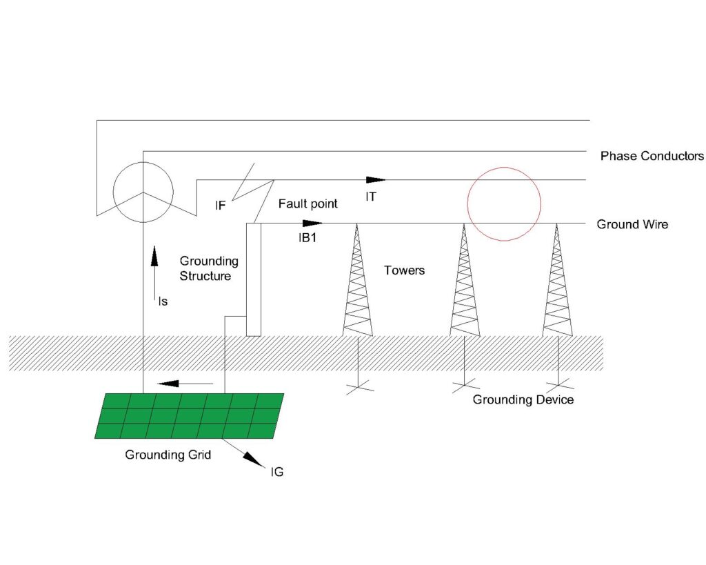
When a short-circuit occurs inside the substation, as shown in Figure below, the total ground fault current IF divides into three components, the component IS flows through the grounding grid to the transformer’s neutral. The component IB1 flows to the neutral of the transformer via overhead ground wire and grounding device, while the remaining component, IG flows to the neutral of the transformer via earth. It may be noted that the component IG cannot be returned through metallic components and overhead ground wires.

Therefore, IG is the grounding grid current that flows to the earth from the grounding grid, and it can be calculated using the following equation
![]()
Where, IT = IB1 + IG = IF – IS , IT is the total return current that isn’t handled by the grounding grid directly.
Kf1 = IB1 / (IF – IS) = IB1 / IT , which is the fault current division factor for the return current that uses overhead ground wire and tower grounding device.
While analyzing the overhead line and uniform towers, fault current division factor for ground wire and tower grounding device, Kf1 can also be calculated by
![]()
Where, s is the number of tower spans, ZGO is the zero-sequence impedance of overhead ground wires per km, ZMO is the zero sequence mutual impedance between ground wire and phase conductor.
ZGO can be calculated using the following equation
![]() (Ω/km)
(Ω/km)
where rd is the phase conductor’s resistance per unit length (in Ω/km), n is the number of sub conductors in every phase line, am is the equivalent radius of the bundled conductor in meters, Dg is the distance between the ground wire and its equivalent mirror and D is the geometric mean distance between two split-conductors, 0.15 is the empirical constant which indicates to the real part of mutual impedance, 0.189 j is the imaginary inductive reactance component.
ZM0 can be expressed as
![]() (Ω/km)
(Ω/km)
where Dbx is the geometric mean distance between the phase conductors and ground wire
The mutual impedance results from high fault current in the phase conductor, inducing a voltage in the overhead ground wire via mutual inductance. It depends upon the separation between the phase and ground conductor. A high separation results in weaker electromagnetic coupling and low mutual impedance.
A higher ZMO relative to ZGO reffers to more fault current returning via overhead ground wire and tower grounding devices rather than via earth. While if ZMO becomes lower, most fault current will return via earth, which will increase the touch and step voltage of the substation.
β in above Equation can be calculated by:
![]()
Where, ![]()
Where RT is the tower footing grounding resistance.
When there are plenty of towers such that number of tower span, s >5, the 1st equation can be simplified into
![]()
The tower footing resistance RT is always larger than the substation’s grounding resistance R. Under the assumption that R tends to 0, meaning that the substation is absorbing all the nearby current, then the above equation can be simplified as
![]()
The result calculated gives a conservative solution, reffering to worst possible tower grounding performance. Which means most fault current goes to the earth contributing to high GPR and high risk of step and touch voltage. If this equation is involved in design, GPR and touch and step voltage calculations will be over estimated thus making the design more safer.
Thus, the fault current division factor for the substation grounding will be
![]()
Fault Current Division Factor Outside a Local Substation

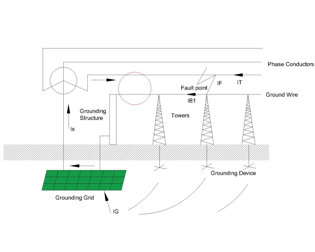
When the fault occurs outside a local substation, as shown in Figure, the current distribution changes compared to previously discussed internal fault. IF is the total ground fault current, IS is the part of the fault current that flows through the transformer’s neutral, the component IB1 is the part of IS returning via the overhead ground wire connected through the grounding device and IG , the component of IS flows through the grounding grid to the earth. IG can be calculated by
![]()
where Kf2 is the fault current division factor of the overhead ground conductor which tells us how much current is entering via overhead ground wires and grounding devices instead of the earth.
The fault current division factor Kf2 for a fault outside a substation can be calculated by
![]()
When the external fault occurs at a place which is at a distance of 10-20 tower spans, the first term of the above equation becomes much smaller due to exponential increase in the denominator. Hence, it can be neglected.
![]()
This equation also results in over estimation of IG because lower the fault current division factor,Kf2 , higher will be the current flowing through earth IG ,which results in safer design for equipment and personnel.
This is how the faut current division factors for both internal and external faults is derived.
In grounding design, generally, we use the Equations
![]()
and ![]()
And take the maximum current flowing into the ground IG from internal and external faults. The consideration of maximum IG results in a conservative design which takes into account the worst possible scenerio of the maximum possible IG, thus making the design safer.
This article is a part of the Safety and Earthing page, where other articles related to topic are discussed in details.

