Principle to Determine Maximum Grounding Grid Current
The maximum grounding grid current, IG is the maximum fault current that flows into the earth from the grounding grid for an internal fault at the substation or vice-versa for any external remote fault outside the substation. It is the most critical factor of consideration in the grounding grid design.
Table of Contents
This maximum grounding grid current dictates the ground potential rise of a substation, generates the maximum step and touch potential which can have dangerous consequences to both equipment and personnel.
When ground faults occur, the earth acts one among the return paths for the fault current but it should be noted that not the entire fault currents returns via the earth. A fraction of the fault current flows into or returns via the earth. Most of the fault current choses to flow or return via transformer’s neutral or the tower grounding or via over head ground wires thereby mostly bypassing earth.
The ground grid current depends on various factors, like fault location, distance from the substation, impedance of the ground path, fault current division factors, transformer’s neutral grounding configuration, system configuration changes and many more. So, it becomes difficult for any formula to give out which fault and at what location causes the maximum grounding grid current.
Types of Substation Ground Faults Which Can Generate Maximum Grounding Grid Current
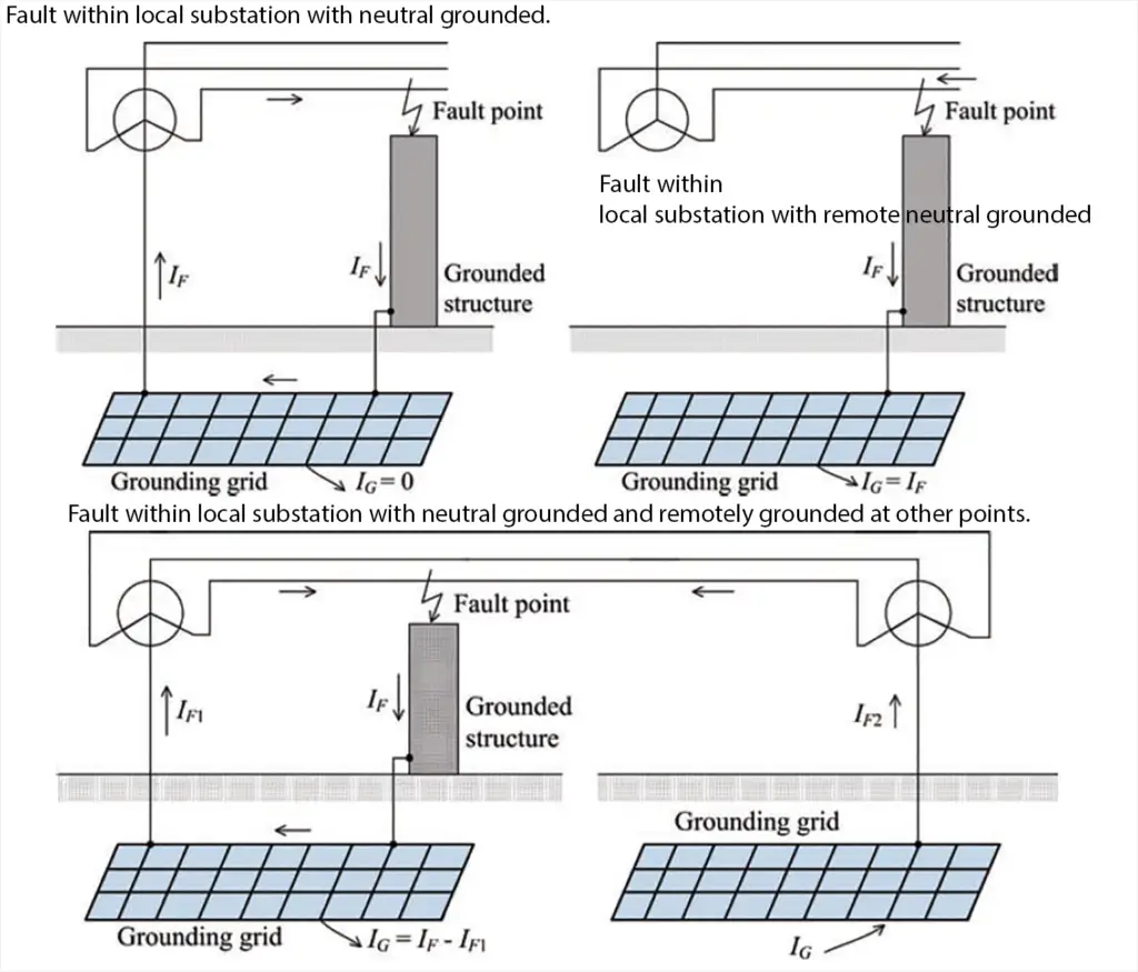
The earth faults which can have substantial effect on the grounding grid current and behaviour are.

Type 1
Fault has occured within the substation where the neutral is only grounded locally and the fault current flows from the fault point to the grounded neutral via the grounding grid. No fault current flows into the ground. This type contributes to minimal ground potential rise.
Type 2
Fault has occured within the substation with a remotely grounded neutral. The fault current flows into the earth via grounding grid. The GPR is very severe.
Type 3
The fault has occured within the substation, with neutral grounded locally and remotely, the fault current gets splitted and returns to the local neutral via the grounding grid and also returns to the remote neutral via the earth. Significant GPR because of the part of fault current flowing to the remote neutral via the earth.
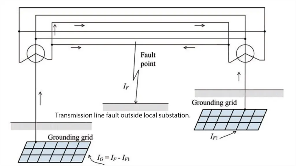
Type 4
Fault has occured in the transmission line outside of the substation, where there both local and remote neutral grounding, the fault current returns via remote grounding to earth, from earth to the substation grounding grid then to the local grounded neutral. GPR rises because of fault current returning via earth.

Maximum Grounding Grid Current
The fault current division factor is the ratio of the portion of fault current flowing into or out of the grounding grid via earth to the symmetrical fault current.
The maximum grounding grid current in terms of decrement factor is given by
IG = Df Ig , where Df is the corresponding decrement factor of the fault duration tf; and Ig is the rms symmetrical grid current in A.
The rms symmetrical grid current, Ig is the portion of the symmetrical fault current which flows into or out from the grounding grid via earth, which can be denoted as:
Ig = Kf If ,
where If is the rms value of symmetrical fault current in ampere, and
Kf is the fault current division factor, which is the ratio between the portion of fault current that flows from the grounding grid to the ground and the amplitude of the fault current.
However in reality, the fault current division factor varies throughout the event of fault, and the variation is dependent upon the attenuation velocity related to the decaying of dc offset and the fault clearing time of the protection system installed.
However, for the ease of calculation, it is assumed that the fault current division factor Kf remains unchanged during the fault event.
The rms value of the symmetrical fault current If thus can be obtained by:
If = 3I0 , where I0 is the zero-sequence fault current in Ampere.
Therefore, maximum grounding grid current, IG = Df * Kf * 3I0 , which is proportional to the zero sequence component of the fault current.
This article is a part of the Safety and Earthing page, where other articles related to topic are discussed in details.

