Table of Contents
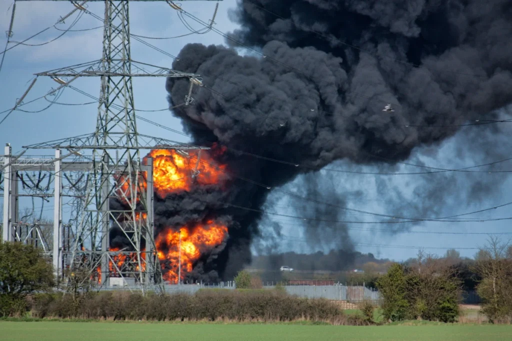
Electrical Faults are abnormalities of electrical parameters, either voltage or current, or both in a stable power system. Electrical faults are generally caused by equipment failure, human error, and environmental conditions. Electrical faults can cause significant economic damage and have the potential to cause fire hazards risking human life.
CLASSIFICATION OF ELECTRICAL FAULTS
Broadly electrical faults can be classified as i) Shunt Faults, ii) Series Faults
Shunt Electrical Faults (Short Circuits)
A short circuit is when the current does not flow in the desired circuit towards the load but takes a short low resistance path either to the ground or involving other phase conductors. This majorly occurs in instances of insulation failure in the power system. The flow of current increases heavily as current encounters little to no impedance, with a voltage drop during a short circuit.
Short circuits can be full and partial. When the impedance in the circuit is zero, then the fault is a dead or full short circuit. However at times, when the impedance is non-zero but less than the load impedance, it forms a parallel circuit with the load and is called a partial short circuit.
During a short circuit between a phase and ground or phase-phase conductor, an arc is formed during the fault. This electrical arc is formed basically due to the ionization of air between the conductor and grounded object or other phase conductors (with failed insulation). This type of fault is called an arcing fault where the fault impedance is only the impedance of the dynamic arc. Which according to Warrington’s model is:
R = 8750 ( S + 3 u t ) / I1.4
Where S is the gap in feet, u is the velocity of air in mph, t is the time in seconds, and I is the fault current in amperes.
Shunt Faults can be categorized into:
i) Symmetrical Faults:
When all three phases of a power system are equally affected with the same fault current magnitude in each phase, creating a balance, such faults are called symmetrical faults.
The Line-Line-Line fault is a symmetrical fault in which three phases are physically joined with zero impedance and equal fault current in each phase. Since it is a balanced fault hence only positive sequence component will be present in this case.
Line-line-line-ground is another type of symmetrical fault in a power system. This is also a three-phase balanced fault but here zero and positive sequence current components will be present.
The symmetrical type of faults are very rare in occurrence but are most deadly because of the highest fault current levels.
ii) Unsymmetrical Faults:
These faults in the power system are unbalanced faults because there exist unequal magnitudes of current and voltage in the three phases. These faults contain both positive and negative sequence components along with zero sequence components during ground connection.
i) Line-Ground ii) Line-Line iii) Line-Line-Ground are three types of unsymmetrical faults in the power system.
Faults consisting of a ground connection with phase conductor(s) are termed ground faults. Whereas, different phases establishing a connection results in a fault called a phase fault.
| Fault Type | Positive sequence | Negative sequence | Zero sequence |
| L-G | Yes | Yes | Yes |
| L-L-G | Yes | Yes | Yes |
| L-L-L-G | Yes | No | Yes |
| L-L | Yes | Yes | No |
| L-L-L | Yes | No | No |
Insulation failure often results in shunt fault. The insulation of an electrical installation can fail due to frequent over voltage switching surges or lightning surges. However, the insulation can also be weak due to the following factors resulting in failure:
- Aging
- Temperature
- Rain, hail, snow
- Chemical pollution
- Foreign objects
- Other causes
Effect of Shunt Faults in a power system
Electrical faults cause heavy current flow through the system liberating excessive heat. And if this condition persists in the system for a short time duration, the power system elements or connected equipment will undergo maximum damage because of the high fault current.
Even on the encounter of small resistances, fault current in Kiloamps liberates heat and the excessive heat can cause a fire. This heating can further disintegrate the insulation, weakening it. Excessive short circuit current can induce mechanical damage and undue stress in the winding of transformers, motors, and generators. Sometimes busbars of substations and transmission line conductors also experience attraction and repulsive force during short circuit conditions if spacing between them is not appropriate.

Data analysis from past experiences of power system operation shows that all electrical faults are not equal in occurrence and severity. Single line-to-ground faults (L-G) are the most likely electrical faults whereas the fault due to a simultaneous short circuit between all three lines, known as the three-phase fault (L-L-L), is the least likely.
list of Electrical faults
Fault | Probability | Severity |
L-G | 85% | Least severe |
L-L | 8% |
|
L-L-G | 5% |
|
L-L-L, L-L-L-G | 2% | Most severe |
Total | 100% |
|
The probability of faults in different elements of the power system is different. The overhead line experiences more faulty conditions than the underground cables do. Transformers and generators with enhanced safety still experience few fault instances.
Power system element | Probability of faults |
Overhead lines | 50 |
Underground cables | 9 |
Transformers | 10 |
Generators | 7 |
Switchgears | 12 |
CT, PT relays, control equipment, etc. | 12 |
Total | 100% |
Series Electrical Faults
Series faults are basically open circuit faults. These faults do not result in catastrophes. However, it can be said from field experience that most of the open conductor faults convert into some kind of short circuit fault as the faulty conductor touches other phase conductors or ground. However, there have been instances where an open circuit fault resulted in a dangerous outcome. For example, the secondary circuit of a current transformer and the field circuit of a DC machine if open-circuited, can result in complete equipment failure sometimes explosion.
It may be noted that the line between the normal and faulty conditions is not crisp. There are certain operating conditions inherent to the operation of the power system that are definitely not normal, but these are not electrical faults either. Some examples are the magnetizing inrush current of a transformer, the starting current of an induction motor, and the conditions during power swing.
BOUNDARY CONDITIONS
For three-phase fault
A three-phase fault occurs when all three phases are shorted physically. The boundary conditions for three-phase faults are VA = VB = VC and IA + IB + IC = 0.
Single line to ground fault
A single line to ground fault occurs when a phase is shorted with the earth. Assuming the fault impedance to be ZF the boundary condition for an L-G fault considering the shorted phase as ‘A’, VA= IA ZF, IB = 0, IC = 0, The fault current IF = IA = Ia0+Ia1+Ia2=3Ia1, where Ia0, Ia1, Ia2 are the zero sequence, positive sequence, and negative sequence currents respectively
Line to Line faults
A line-to-line fault occurs when two phases are shorted. Assuming the phases being B and C phase and fault impedance to be ZF the boundary condition for an L-L fault is, VB= VC +IB ZF, IB = 0, IA = 0, IB+IC = 0 or IB = -IC The fault current IF = IB = -j√3Ia1, where Ia0, Ia1, Ia2 are the zero sequence, positive sequence, and negative sequence currents respectively.
Double Line to Ground Faults
Double line to ground faults occurs when two phases are shorted with the earth. Assuming the shorted phases are B and C, the boundary conditions become IA=0, VB=VC= (IB+IC)ZF = 3Ia0ZF. The fault current is given by IB+IC = 3Ia0, where Ia0 is the zero sequence current component.
STEPS FOR REDUCING THE ELECTRICAL FAULTS
Earthing:
Earthing must be proper in an electrical substation and must be checked for any abnormal values. For substations, the earthing resistance must be 1 ohm or below.
Visual inspection:
Visual inspection must be carried out in the switchyard to detect any abnormalities like wear of conductors etc so that preventive measures can be taken before the occurrence of any faults.
Testing:
Testing of electrical equipment must be done periodically or as suggested by the manufacturer of the equipment to ensure proper functioning as per the designed specification. Insulation of equipment must be tested at regular intervals.
Maintenance:
Maintenance includes the tightening of the clamps and connectors which reduces the temperature and resistance if any loose connection persists, cleaning of the insulators, lubricating the gears of the isolator, and other mechanisms. Jungle cutting and corridor clearing, an important tasks of maintenance of the transmission lines as it is often observed that most electrical faults occur due to tree branches touching the live conductors of the lines, it is therefore important to keep the corridor clean.
The occurrence of electrical faults can be minimized by following the above-mentioned steps but it cannot be fully nullified.
This article is a part of the Substation Guide, where other articles related to substation are discussed in details.

