Arrangement for capacitor bank can be configured based on available voltage levels, protection phillosophy and required relaibility and flexibility of use. Most substations uses a star connected bank, however distribution units may be star or delta connected. Some system uses H arrangement in the units per phase of the bank so that current unbalance can be found by using properly sized current transformer in each phase.
Table of Contents
Units connected in grounded Star or wye
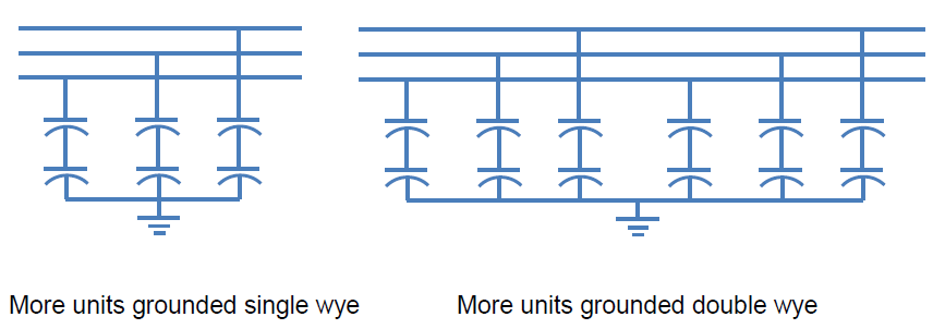
The grounded star capacitor banks utilizes both series and parallel connected capacitor units for each phase with a neutral for low impedance grounding.
The benefits of the grounded capacitor units are:
The voltage surges can be effectively grounded via low impedance grounding.
No surge arrester is needed as capacitor unit can absorb it.
Low-impedance grounding can also absorb high frequency currents and harmonics acting as a filter.
It makes the transient recovery voltage of circuit breakers and switching devices weak which helps to stop re establishment of the arc.
Some disadvantages of grounded wye shunt capacitor banks are:
Harmonics can cause interference in the nearby telecom circuits.
System protection can malfunction because of circulation of inrush currents and harmonics.
High frequency and high amplitude of current can cause CT secondary voltage to rise, which can be restricted with the use of phase connected series reactors.
Multiple units connected in series phase to ground – double Wye
When capacitor banks sizes up very big, it becomes impractical for connecting more units for sizing up and fuses for protection. The capacitor bank is then divided into multiple star connected systems. Grounded single star banks and multi star banks have similar features and results. All neutrals of multi star units can be linked to a common grounding.
The double star arrangement for capacitor bank, each phase is linked with two capacitor unit groups connected in star which creates two seperate neutrals. In normal operating conditions, the zero sequence current components appreas symmetrically in both the neutrals and remain balanced. However, when one unit breaks down, it creates a voltage imbalance and current flows through the neutral which can be easily detected. The system is simple, offers reliablity and protection with the use of simple unbalance protection relays.
If the banks has internal or external fuses, time co-ordination will be required. However for fuseless systems, the relay can operate faster without time delay for any fuse to operate. If the current limit of the capacitor unit is exceeded, adding a parallel strings of capacitor elements will solve the issue with increasing reliablity.

Units connected in ungrounded wye
Units with ungrounded star connections basically has the neutral isolated electrically or it can be said that the neutral of such a system is kept floating. This arrangement for capacitor bank has one or more capacitor units connected between phase and neutral. Since the neutral is not grounded, the zero sequence current components gets eliminated. In the case of a ground fault, the fault current is also lower as the neutral is not grounded.

Delta arrangement for capacitor bank
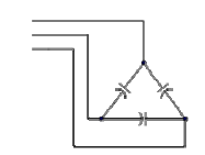
This arrangement for capacitor bank are used for distribution voltage levels below 33 KV. In this arrangement each capacitor unit with a single series group is connected between phase to phase as shown in the diagram.

Since connected between phases, each capacitor group must be rated to line voltage. In this arrangement if one leg of the delta has a failed capacitor unit, the other two legs donot suffer from overvoltage stress, which is not the case in star connected arrangements. Also because the faulted leg gets isolated and without neutral, current imbalance cannot be measured, therefore this arrangement for capacitor bank doesnot requires a unbalance protection system.
Absence of neutral, restricts the circulation of zero sequence current and harmonics making this arrangement for capacitor bank immune to these transients. However, it also makes the arrangement less sensitive to system faults.
Where one series group of capacitors is used, the individual capacitor fuses should be capable of interrupting the system short-circuit phase-to-phase fault current. This design may necessitate current limiting fuses.
If internally fused capacitor units are used, then unbalance detection is required to detect a capacitor with failed elements. There is no indication of a blown-out fuse. Two or more series groups of capacitor elements are normally needed so that each capacitor unit enables the internal fuses which can interrupt the fault current.
Static var compensators usually use the delta connection for the thyristor-switched capacitors (TSCs) to simplify the controls and optimize the use of the thyristor valve.
H arrangement for capacitor bank
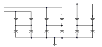
In this arrangement for capacitor bank, each phase of the bank is divided into two arms representing the alphabet H. The arms are bridged with a current transformer installed in between. During normal operating condition the connected current transformer senses no current as there is no differential current in the splitted arms. But whenever there is a faulted element in one arm or a blown fuse, current differential between the arms gets created and sensed by the CT which is then picked up by the protective relay. The CTs used are very sensitive and detects deflection of current even due to a single capacitor element fault. Therefore, this arrangement is very suitable for large capacitor bank at higher voltage levels.

This article is a part of the Energy storage and reactive power compensation page, where other articles related to the topic are discussed in details.

