Shunt capacitor Banks
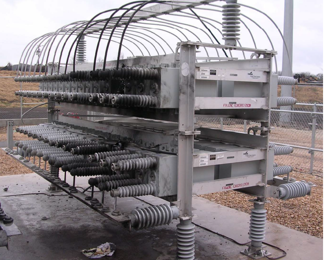
Shunt capacitor Banks or SCBs are used in the power system as they deliver capacitive reactive power compensation that aids in improving power factor. These capacitor banks are easy to install and maintain providing an affordable and simple solution to power factor correction needs.
Table of Contents
Other than power factor correction, capacitor banks also provides the following:
- Load side voltage improvement,
- Helps with voltage regulation,
- Reduction in power loss

The reactive power that the capacitor bank generates is a function of the square of the system voltage. Therefore, when the system voltage is critically low, it delivers only small amount of reactive power.
The capacitor unit
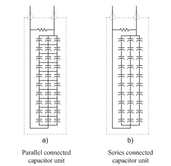
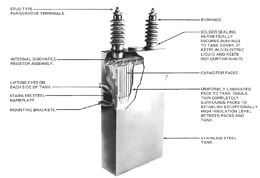
Many capacitor elements connected in parallel or series arrangement inside a case forms the capacitor unit. This unit is of utmost importance with a resistor that reduces the residual voltage functions as a discharge element. These units are rated in volts and Kvar. These units are connected together to form the shunt capacitor bank.

Protection of shunt capacitor bank from over current is generally done by the fuse. However surge arresters are used for over volage protection. Protection against failed capacitor elements can be done by using a current transformer in the neutral of the star connected configuration, thus detecting unbalanced currents in the neutral. Harmonics filters are used for protection against the harmonic currents. Large capacitor banks also uses differential protection.
Below the rated voltage and frequency levels, capacitor banks are mostly brought in service, as the reactive power is a function of both these parameters. The reactive power generated in a capacitor element is a function of both voltage and frequency as Kvar = V2/Z ; Z = XC and XC = 1/2𝜋fC

For use in AC power system by shunt interconnections, standardization of the capacitor elements are given in IEEE Std 18-1992 and Std 1036-1992.
As per the IEEE standards,
The capacitor units are designed for continuous operation till 110% of rated terminal voltage with the crest voltage below 1.2×√2 times the rated RMS voltage, considering harmonics but neglecting the transients of the system.
The shunt capacitor units shall be capable to handle 135% of the rated system current without excessive temperature rise.
The reactive power generation in the capacitor units shall be in the range of 100% to 115% of rated reactive power at rated AC voltage and frequency.
Shunt capacitor units shall not be put into continuous service above 1.35 times the rated reactive power because of impacts from
- Voltage exceeding the 110% rated voltage at system frequency.
- Harmonic voltages and transients at system frequency.
Shunt capacitor bank arrangements
The fuse aids in the protection of shunt capacitor element and their placement either inside or outside the capacitor element is an important parameter for the design of shunt capacitor banks. The placement can impact the protection of the capacitor bank as it directly relates to the faults in the capacitor elements. Various characterization of capacitor banks based on fuse arrangement in the unit are discussed below:
External fuse
A fuse, externally installed between the terminals of capacitor unit for providing protection to every shunt capacitor element. Because the external fuse can clear a high-current fault, with high arc energy handling capacity therefore, shunt capacitor elements can be rated for higher voltage. Thus higher the rated voltage of the capacitor element, lesser will be the number of capacitor units used.

A faulty capacitor element generates heat, this heat binds the foil of the element together to create a short circuit. This shortcircuit enables the current to flow between other parallelly connected capacitor elements. This makes the remaining capacitor elements operational with increased potential across. Further alike faults will create a domino effect raising voltage across the element to dangerous levels. Therefore, similar consecutive faults in the same capacitor unit will initiate the fuse trip, thus isolating the capacitor unit.
The series connected capacitor element groups are connected in parallel for better current handling in the externally fused unit. If the number of series connected capacitor units or parallel connected capacitor elements of a capacitor unit is increased, the unbalanced current in the neutral connection can be reduced. However, the kilovar rating of the individual capacitor element has to be small because fewer parallel elements are required for the unit to be operational with faulty elements.
If Kvar rating of individual element is higher, number of parallelly connected units will be less and if one unit fails, the entire rating of the unit will go down drastically. This is done basically to increase redundancy and continuity of service.
Shunt capacitor bank with internal fuses
Fuse is inside the capacitor element. The fuse is basically a wire encapsulated in a wrap which can limit current and as well as heat from arc . When there is a fault in the capacitor element, the fuse acts to cut off the faulty element only. The remaining elements connected in parallel, remains operational with some increased potential across.

In internally fused shunt capacitors, less number of capacitor elements are connected in parallel to limit the current imbalance and better fuse co-ordination.
Fuseless shunt capacitor banks
Fuse-less shunt capacitor banks are used where the short circuit of one capacitor element does not leads to high voltage on the operational elements remaining. These banks are basically used at a voltage levels 33KV and above. The capacitor units are basically designed such only two bushing extrudes out of the case while the remaining stays inside, insulated. The capacitor units are connected in series for a single phase installation, that is between phase to neutral or between phases in a three phase system. The protection of these banks is basically inside the unit where if a element fails, it breaks and gets welded keeping the unit healthy and operational. The voltage of the broken down element is distributed among the remaining operational series connected elements. The energy discharge is minimal because of the indirect parallel connection of the capacitor units.

Unfused Shunt Capacitor Units
In the unfused shunt capacitor bank, the capacitor units of the capacitor bank uses a series/parallel connection arrangement. The protection in this arrangement is done at the capacitor bank level and not in elements by using circuit breakers and relays. This arrangement is used for application catering to below 33KV voltage level, where a series connection of capacitor units is not found to be practical. Unlike externally fused capacitor bank arrangement, this arrangement requires fewer capacitor units connected in parallel.

This article is a part of the Energy storage and reactive power compensation page, where other articles related to the topic are discussed in details.

