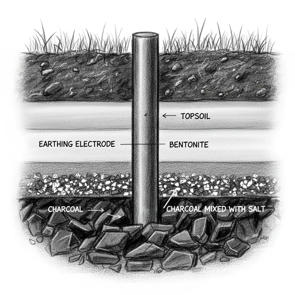
Earthing layers are basically layers of conductive materials like charcoal, bentonite, sand, and salt or any special backfill compound, which is placed around the electrode in order to improve the soil conductivity. It is the earthing layer which is responsible for uniform and low resistance interface between the grounding electrode and the surrounding earth. It improves the performance, reduces the resistance and ensures stable and safe dissipation of high fault current in to the earth.
Multiple earthing layers are often used in grounding system for various causes like reducing the soil resistivity, maintain moisture around the electrode, increase the fault current dissipation area, preventing the seasonal resistance fluctuations and more.
Table of Contents
Purpose of Earthing Layer
Improvement in soil conductivity: Earthing layers of bentonite, charcoal, salt and other backfill compounds increases the concentration of ions and moisture retention around the electrode. As the electric current in soil moves through these ions, presence of the earthing layer improves the soil conductivity enhancing the grounding system performance during faults.
Reduction in overall earth resistance: Use of multiple earthing layer creates a large, uniform low resistance zone around the grounding electrode. This increases the effective contact surface between the electrode and earth, allowing the current to move more uniformly and spread out. With the drop in the contact resistance between the electrode and earth, the total grounding resistance also decreases significantly ensuring safe high current dispersion.
Increase fault current dissipation area: As the earthing layer expands the conductive zone around the electrode, the fault current dispersing also expands with a wider radius. This ensures that the fault current is not concentrated and spreads efficiently, reducing the localized heating and soil ionization.
R = (ρ / 2πL) ln (4L / deff)
R is the grounding resistance in Ω, ρ is the soil resistivity in Ω·m, L is the length of rod in m and deff is the effective diameter of the electrode.
Considering the drop in the resistance, effective diameter of the electrode or the fault current dissipation area increases.
Safer step and touch potential: With the application of earthing layer, the earth resistance is significantly lowered, therefore increasing the fault current dispersion in a wider area. This reduces the voltage gradient on the earth surface with a smooth distribution, which in turn reduces the risk of dangerous step and touch voltage.
Materials used in Earthing Layer
Natural soil: Natural soil is the primary medium of grounding with a varied resistivity of 10-1000 Ω·m depending on moisture, temperature and composition. Soil with high clay content and electrolyte, exhibits a low resistivity of 10-50 Ω·m because of increased ion mobility. While dry sand, gravel and rocky terrain has minimal free ions resulting in poor conduction. Moisture content above 15-20% lowers the resistivity as it forms a continuous electrolytic pathway for the conduction mechanism to stabilize. Temperature on the other hand increases the resistivity of the soil roughly by 2% per °C drop near freezing as transition of water to ice nearly eliminates the ionic mobility.
Charcoal: It is the most common conducive backfill material used in the surrounding of grounding electrode for lowering the soil resistivity and stabilize the electrode soil interface. With resistivity typically ranging between 5-20 Ω·m, charcoal creates a low resistance, iron rich zone, which enhances the current dissipation. The highly porous microstructure of charcoal increases the effective surface area with superior moisture absorption and retention even in dry conditions, which forms the electrolytic pathways for the charge transportation during fault surges.

The carbon-based matrix of charcoal minimizes the electro-chemical corrosion of the electrode by creating a buffer layer between the metallic electrode and the aggressive chemistry of soil, mitigating the oxidation. Also, the thermal stability of coal helps in dissipation of heat, produced during fault, thereby preventing the localized ionization of soil and thermal runaway around the electrode.
*Thermal runaway is a positive feedback heating process that occurs during extreme high fault current entering the ground. In extreme cases, electrode temperature rises to 600 °C causing the carbonization of backfill resulting in increasing earth resistance, increasing GPR, increase touch and step voltage, and reduction in fault clearing speed.
Salt (sodium chloride): Salt is also used as a electrolytic soil conditioning agent which artificially reduces the resistivity of the electrode-soil contact or interface. The ionic conductivity increases dramatically as Na+ and Cl– ions dissociates in the surrounding soil lowering the localised resistivity of the soil to 2-10 Ω·m depending on the availability of the moisture. The high ion concentration enhances the charge transportation, reducing the polarisation impedance and thus improving the current injection capability of the grounding electrode.
However, during rainy season, as NaCl is highly soluble, it migrates away from the electrode zone leading to temporal instability in the resistivity of the soil. It results in inconsistent grounding performance across season and requires charging when degraded. Also presence of chloride increases the electrochemical corrosion in copper and galvanised iron electrodes by lowering the pH value of the zone and increasing the corrosion current density at the interface of the metal and soil.
Bentonite: Sodium bentonite is a high swelling montmorillonite clay with a resistivity of 2-3 Ω·m when it is hydrated. It has a capacity of water absorption up to 5 to 8 times its volume, which allows it to maintain the moisture around the electrode. By forming a stable and low resistive electrolyte around the electrode, it influences the current conduction process. Bentonite has excellent cation exchange capacity, moisture retention and non-corrosive property which results in long term excellent grounding performance of the earthing layer.
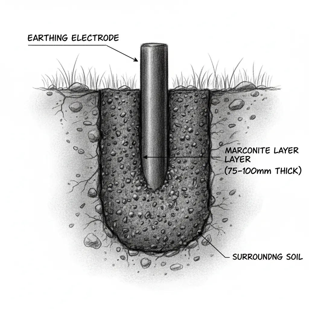
Marconite or conductive concrete: It is basically a conductive aggregate which has extremely low resistivity of round 0.1 to 1 Ω·m. When mixed with cement, it forms permanent conductive concrete encasing the electrode. It has a high compressive strength and offers stable performance irrespective of soil moisture. It also is non corrosive to the metallic electrodes and thus is very much suitable for substation, dry terrain and critical grounding installations.

Depth and placement of earthing layer
Earthing pits are typically installed at a depth of 2 to 3 meters to reach the moist, low resistive soil for optimal grounding performance throughout seasons. Earthing layers are placed around the grounding electrode placed with a thickness of 150 to 300 mm uniformly, which reduces the local resistivity and improves the moisture retention.
It may be noted that salt layer is not separately laid but mixed with the charcoal layer. The bentonite earthing layer must be placed under the top soil. The marconite layer is placed with a thickness of 75 to 100 mm encasing the grounding electrode. It can be noted that IEEE-80 does not recommends the use of salt layer as it promotes the corrosion and washes out easily but industry still uses it.
Installation guide
The process begins by excavating the soil, typically 3 m deep, depending upon the resistivity of the soil. The electrode (copper rod, GI pipe or plate) is then placed at the center of the pit. The excavated pit is then filled layer by layer with materials like charcoal, salt, bentonite and other backfilling compounds in layers of 150-300 mm in order to improve the conductivity of the local zone around the electrode.
Each earthing layer is then watered properly to ensure moisture absorption and compacted to remove the air gaps. After surrounding the electrode fully, the pit is filled with native soil and then compacted. The earthing conductor is securely connected to the electrode and the pit is sealed with a concrete chamber marked for identification and maintenance.
This article is a part of the Safety and Earthing page, where other articles related to topic are discussed in details.

