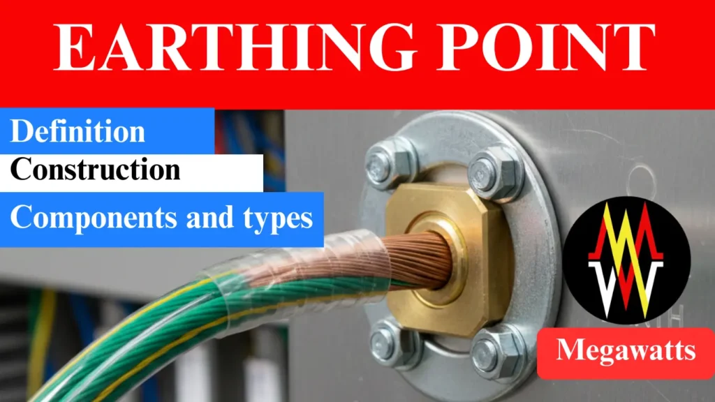
An earthing point is the physical point where the electrical installation connects to the earth using an electrode, earthing conductor or busbar. In installation such as a substation, industries, panel boards in control room are often connected to the earthing electrode via common bus bar. The earthing point serves as a reference point for the fault current to return following the low impedance path to the ground. Since all metallic enclosures, structures are bonded at the earthing point, it helps maintain all the metallic parts at zero potential, thus preventing hazardous shocks.
A proper earthing point provides a low impedance path to the fault current to dissipate in the earth, thus stabilizing the system voltage, preventing electrical shocks during fault, and allowing the protective devices to function precisely. It is to be noted that an earthing point is a single physical connection, where as the grounding system includes the entire grounding network composed of electrode, conductors, grid, bond, and protective path.
Table of Contents
Purpose of Earthing point
Earthing point ensures all the fault current flow through the one defined path, which allows the protection device to perform with enhanced reliability. Multiple path towards the earth causes circulating currents which are responsible for overheating, nuisance tripping and unpredictable touch voltages. An earthing point (single), resolves these issues. This single point also acts as a measurement point for earth resistance, which is essential for accurate testing and system compliance. The earthing point maintains a zero-volt reference for the installation, preventing the neutral shifting and causing voltage imbalance. The earthing point ensures predictable system behaviour under normal operation as well as faulty condition, thus simplifying the design and improving safety.
Location of Earthing point
The location of the point should be strategically selected to ensure lowest possible impedance path to earth. Ideally the point should be located near the main switchboard, transformer body, equipment structure or an earth pit, which will allow a short and direct run of grounding conductor. Reducing the length of the grounding conductor, reduces the resistance, voltage drop and inductive effect (2πfL) during the fault condition which ensures faster operation of the protective devices.
It is also to be taken care of that the point must not interfere with the metallic pipelines, water lines, building foundation or underground structure and must be positioned away from these. Otherwise, there will be risks of creation of parallel path for the current which would cause corrosion. The earthing point must be accessible for inspection, testing and maintenance. In large installations like substation, the point must be integrated smoothly with the earth grid for ensuring consistent potential across the equipment.
Construction and components
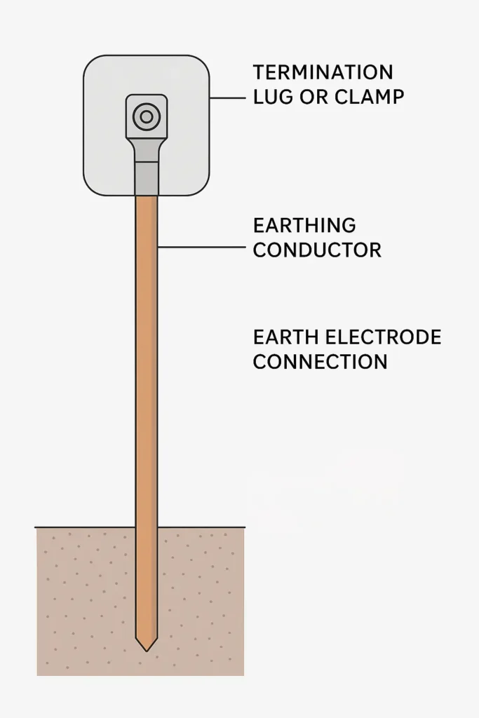
The earthing point is the physical interface from which the electrical installation connects to the earth safely. The construction of this point ensures a reliable low resistance path through which the fault current will enter the stable system grounding. Among the components, a termination lug or clamp is the first one which establishes a secure mechanical and electrical connection between the earthing conductor and the equipment frame, panel or grounding busbar. These lugs or clamps are made from copper or tinned copper, which helps minimize the contact resistance.

The point is then linked to the earth electrode, which is essentially a rod, pipe or a plate rigged in the soil. It is this electrode which dissipates the fault current coming through the point to the earth safely. For safe dissipation the electrode must be sized according to IEEE-80 or IEC 60364. An earthing conductor connects the point to the electrode which is usually copper or galvanized steel. The cross sectional area of this conductor is selected such that it can withstand the maximum fault current without overheating.
The required cross sectional area (S) of the earthing conductor can be given by
S = I x √t / k,
where ‘I’ is the fault current in KA or A, ‘t’ is the fault clearing time in seconds and ‘k’ is the material constant in [A.√s/mm2].
The value of k varies with the conductor material, the typical value of which is 115 for copper, 52 for galvanized steel and 76 for aluminium.
In most installation, like the substation or industry, the point of earthing is housed inside a protective enclosure which is also the inspection chamber. This chamber allows for periodic testing, visual inspection, maintenance and moisture management.
Types
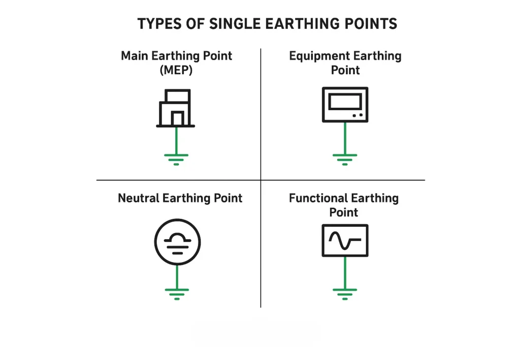
The earthing point ensures that every section of the electrical system has a defined and controlled connection point to the earth, which prevents the parallel path and circulating currents.
Main Earthing Point: This point (MEP) is the primary point where the building or commercial installation connects to the earth electrode, which is the reference node for all the bonding and protective conductors in the system.
Equipment Earthing Point: These points are provided on every equipment frame, panel, enclosure for safe discharging of fault current and maintain safe touch voltage on metal surfaces. This point connects to the MEP via protective conductor.

Neutral Earthing Point: This is the point where the neutral of the electrical system is bonded to the earth. This enables the protective device to function properly and also stabilizes the phase voltage.
Functional Earthing Point: These are special points used for sensitive electronic, communication and control equipment, which needs a clean and noise free reference for proper signal integrity.
Design consideration
The point must use a corrosion resistant connector preferably tinned copper or brass or stainless steel, which will ensure long reliability and increase service life in outdoor and humid environment. Besides, the joints must have a high mechanical strength and proper tightness to maintain low resistance throughout the earthing path as poor tightness and oxidised joints increases the contact resistance significantly, thus effecting the overall impedance.
It is much essential to avoid multiple earthing points for a same system unless the multiple points are properly bonded. It is because multiple unbonded points will create different ground potentials, which will cause circulating current to flow. It will create overheating, malfunction in protective devices, dangerous voltage difference between equipment.
This article is a part of the Safety and Earthing page, where other articles related to topic are discussed in details.

