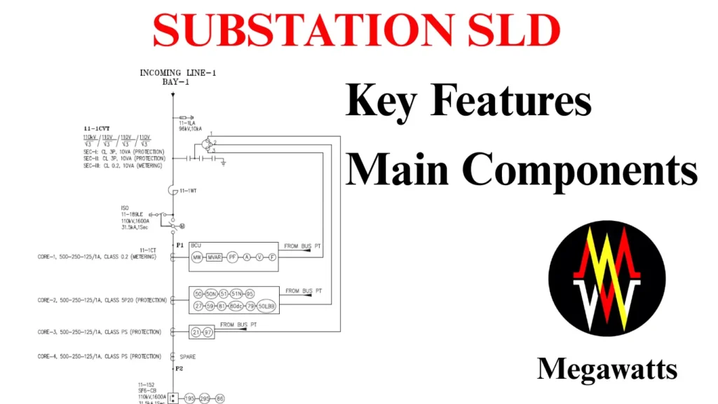
A single-line diagram or substation SLD represents three phases of a power system by a single line, showing the arrangements of different electrical equipment in the switchyard. It shows how the generator, transmission line, circuit breaker, wave trap, capacitive voltage transformers, current transformers, etc, are interconnected with the help of a single line and different symbols representing the electrical substation components.
Table of Contents
Instead of representing the three phases of power separately, a single-line diagram makes use of a single line and makes the diagram more readable and easier to interpret. The main purpose of the substation SLD, single-line diagram, is to get a basic idea about the substation design, equipment arrangement, busbar configuration, and power flow. SLDs are widely used for substations, power plants, renewable energy projects, process industries, etc. With the help of SLD, the planning for maintenance and operation, protection coordination, and power flow analysis becomes easy.
Substation SLD is basically the map or overview of the power system, helping us understand how power is transmitted and distributed.
Main features of a Substation SLD single line diagram.
Simple representation: The representation of three-phase power by a single line makes the system simple and easy to understand.
Standard symbols: Use of standard symbols from IEC or IEEE for various equipment, such as transformers, current transformers, busbars, etc.
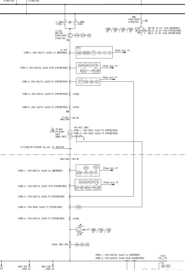
System Voltage: Substation SLD clearly shows the voltage level of the system along with the point where it is stepped up/down.
Power flow: It shows how the power flows from the source towards the load.
Equipment position: It also shows the placement of the equipment in the switchyard, along with the relative position.
Protection and control: It highlights the relay, meters, metering cores, and protection cores of CT and PT, along with the BCU connection where applicable.
Main components of a single-line diagram of a substation
Incoming source: The incoming source to the substation is a point of power entry. It is the point from which the electrical energy enters the substation before being transformed, i.e, stepped up/down. The incoming source for a substation can be a power plant (conventional/renewable) or, grid connection.
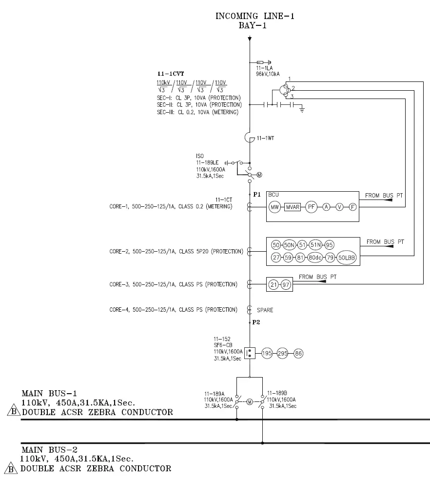
Lightning arrester: A Lightning arrester is the first equipment in any bay that is used for the protection of equipment from traveling surges. In a single-line diagram, the specification of the LA must be clearly written. The specifications are rated voltage of LA which is the rated voltage of the system * √2/√3 and the maximum discharge current of the LA.
Capacitive voltage transformer: It is the second equipment in the substation SLD. It is basically uses a capacitor divider network with a transformer, which replicates proportionally the voltage in the primary side to a low voltage in the range of 110V. The specification of the CVT has to be mentioned in the substation SLD. The specifications are Nominal voltage, capacitance, and voltage ratio, depending on the number of cores. For example, for 2 cores, the ratio will be 220/√3 / 110/√3 / 110/√3.
Wave Trap: A Wave trap is the equipment that follows in the substation SLD, which is used to trap high-frequency communication signals. The single line diagram also specifies its position and specification. The specifications are at which phase the line traps are used, rated current, inductance, and rated short-time current.
Isolator and earth switch: The next equipment to follow is the isolator, which is used for physically disconnecting an already disconnected circuit. It basically adds a safety layer used during maintenance of any equipment in the switch yard. The earth switch is used to safely ground the disconnected circuit for maintenance of the transmission line. The isolator is marked with the digit 89, with A, B depending on the number of isolators in the bay L for line isolator, T for transformer isolator; the earthswitch is marked with 89 E on the substation SLD. The specification includes nominal voltage, rated current, and short-time current rating.
Current Transformer: It the the following electrical substation component, which is basically used to step down the current in the high voltage circuit proportionally to 1A or 5A in the secondary. In the diagram, all the cores of the current transformer have to be drawn, also representing the metering core connection with the trivector meter and BCU, and protection cores with main 1 and main 2 protection relays. The specification of each core of CT with the ratio, class, and burden has to be mentioned in the diagram. It is to be remembered that the P2 side of the CT faces the equipment to be protected.
Circuit breaker: The circuit breaker is designated with the number 52 on the substation SLD and is used for breaking or making a live circuit and quenching the large arc produced during contact separation. The specification of the circuit breaker to be maintained on the diagram includes nominal voltage, rated current, and short-time current rating. The connection of the associated relay has to be shown on the diagram, like the trip circuit supervision relay, the master trip relay.
It may be noted that circuit breakers are accompanied by isolators on both sides, and only the line side isolators have an earth switch integrated.
Busbar: The busbar is the junction point where the bulk power is collected from the transmission line and distributed to the respective load bays. The representation of the busbar in the diagram includes specifications like nominal voltage, rated current, short-time current rating, and also the name and type of conductor used if single/double bundle.
Bay: Bay is the power line circuit that connects a transmission line or a transformer to a common electrical busbar. In the diagram, the bay numbering is done from right to left. Bay numbering of 132 KV will start from 101,102,… 33KV bay numbering starts from 301,302…
Bus Potential Transformer: The bus PT is the component of the substation that steps down the voltage in the primary to 110V proportionally. It is connected to the main bus via an isolator. The BUS PTs have multiple cores for protection and metering purposes. In the diagram, the voltage ratio, number of cores along with class, and burden have to be mentioned.
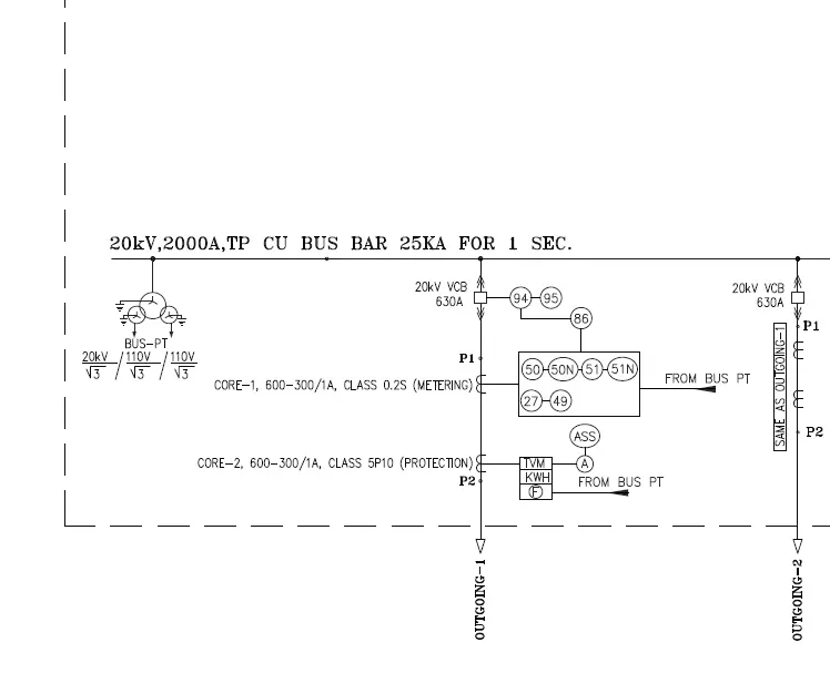
Power Transformer: It is used for stepping up/down the voltage level. It is the central equipment of the substation. In the substation SLD, the specifications for the transformer, such as MVA rating, Cooling type ONAN/ONAF, voltage ratio, vector group, percentage impedance, and steps of OLTC have to be mentioned.
Legends
Various symbols for Substation SLD
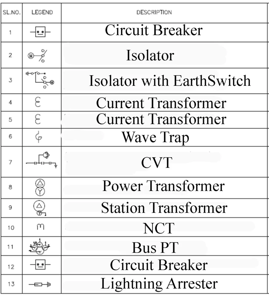
Various ansi codes for protection system used in substation sld
| ANSI CODE | DESCRIPTION |
| 21 | Distance Relay |
| 27 | Under Voltage Relay |
| 81 | Under Frequency Relay |
| 86 | Master Trip Relay |
| 51 | IDMT Over current Relay |
| 51 N | IDMT Earth Fault Relay |
| 50 | Instantaneous Time Over current Relay |
| 50 N | Instantaneous Time Earth Fault Relay |
| 59 | Over Voltage Relay |
| 87T | Transformer Differential Relay |
| 97 | Fuse Failure Relay |
| 99 | Over Fluxing Relay |
| 94 | Anti pumping Relay |
| 95,195,295 | Trip Circuit Supervision Relay |
| 79 | Auto Reclose relay |
| 49 | Over Load Relay |
| 80DC | DC Supervision Relay |
| 64R | Restricted Earth Fault Relay |
| 50 LBB | Local Breaker Backup |
| TVM | Tri Vector Meter |
| SEM | Special Energy Meter |
This article is a part of the page Substation Guide.
