In the substation, the disconnector or Isolator does the same work as the circuit breaker do i.e., isolation of the circuit from the power supply. But the difference is that initially automatic circuit isolation/ tripping is achieved by a circuit breaker or CB due to the arc quenching facility available inside of the CB.
Table of Contents
Thereafter disconnector is used to isolate the CB from the power source & load side (to avoid backward feeding chance) for maintenance purposes of CB/ equipment. Further in the disconnector we do not have any arc quenching medium so we cannot eliminate the arc in the isolator. Therefore, after ensuring the circuit breaker is in an open position then only, we open/operate the isolator.

Working Principle of Isolator:
The isolator is a raw mechanical device. It utilizes gears and has a mechanism to operate a male connecter to fixed female contacts. The gear can be manually operated or it can be operated by an electric motor. The moving male contact makes or breaks the circuit by its rotational motion. The fixed female contacts and the male connector are isolated from the structure with insulators.
The disconnectors are normally equipped with physical interlocks for the operation of the earthswitch. This interlock allows the earthswitch to be operated only when the disconnector is in the open position. Also, the interlock makes it impossible to close the isolator while keeping the earthswitch in the closed position. This enhances the human safety of the device.
Why is an isolator needed?
- Once the CB contact is separated inside the CB pole, but at the terminal the high voltage supplies are available, so we cannot carry out any maintenance on CB equipment.
- Therefore, to isolate the CB terminal from the power source, isolators on both sides of the CB shall be opened. The disconnector in the open position provides power isolation for the CB terminal & CB maintenance can then be carried out.
- “A disconnector is a mechanical switching device used to isolate a circuit from its power source and is normally used to provide isolation of the substation equipment for maintenance”
- They are designed for no load switching although some disconnectors are designed to open or close on low load currents only where there is a parallel current path or where there is no significant voltage difference across the open terminals.
- They are used for busbar sectionalizing, busbar coupling, bypassing circuit breakers/equipment, and isolating circuits.
- The isolator is used in a Tandem arrangement to connect/couple the transfer bus as & when required.
- Disconnectors are essential for the maintenance of line feeders as the operation of CB by human error can cause fatality to maintenance personnel, and mechanical disconnectors, therefore, help to keep a check on the safety during line maintenance.
Ratings of Isolators
Isolators are rated according to the following:
- Rated Voltage: It is the maximum voltage that the isolator will be continuously subjected to. Say for a 132KV system the rated voltage is 1.1 times 132 that is 145KV.
- Rated switching impulse voltage: At substations above 220 KV, the switching surges become predominant where isolators are also rated for maximum switching impulse voltage. For example as per IEC 61936 pt-1 the maximum switching impulse voltage at 420KV level is taken to be 1450KVp. It should be noted that switching surges are transient in nature.
- Rated Current: It is the maximum continuous current that the isolator is designed to handle without any thermal breakdown. It majorly depends on substation capacity and utilization. Some standard values are 630A, 800A, 1250A, 1600A, 2000A, 3150A and 4000A.
- Short time current: It is the maximum fault current that an isolator can withstand for a specific time which is 1 sec or 3 sec. 1 sec time is preferred above 66KV because of the use of the unit protection. In distribution level 3 sec is preferred. This value is mostly decided by the grid fault levels and future expansion. However, some standard values are
| 66KV | 31.5KA for 1 s |
| 132KV | 31.5KA – 40KA for 1 s |
| 220 KV | 40-50 KA for 1 s |
| 400 KV | 50-63 KA for 1s |
- Mechanical Endurance Class: Isolators are also rated according to the mechanical endurance class which gives the number of operations, the isolator will perform without any failure. As per IEC 62271, these classes are
| Class | Type of Isolator | Number of operating cycles |
| M0 | Standard disconnector (Normal endurance) | 1000 |
| M1 | Disconnector with extended mechanical endurance | 2000 |
| M2 | Disconnector with extended mechanical endurance | 10000 |
Types Of Isolator
There are various types of Disconnectors/isolators that are being used in the field.
Horizontal Double break type (HDB)
The Double break type isolators have three loads of post insulators. Among these three, the middle insulator has a tubular contact or flat male that is turned straight through spinning the middle post insulator. At the bottom of the post insulator, a lever method is used for the middle post insulator’s rotation.

Horizontal Double break disconnectors have excellent mechanical stability resulting from a central insulator supporting the moving blade. Both end support insulators can take a high terminal load. This type of disconnector has extensive application at 66 KV and 220 KV levels.
Horizontal center break type (HCB).
Single brake type, which has its arm contact broken into two components. One of these arm contacts is responsible for holding the male contact, and the other one for holding the female contact. A shift is observed in the arm contact due to the rotation of the post-insulator upon which they are fixed. This rotation of the post-insulator is reversed to each other, resulting in shutting the isolator by the arm contact. The counter-rotation opens the disconnector as well as the arm contact.

The rotation of both end insulators of the isolator imposes mechanical limitations on the rated terminal load capability and hence is not suitable for its application at the 765 kV level.
Pantograph type (vertical movement)
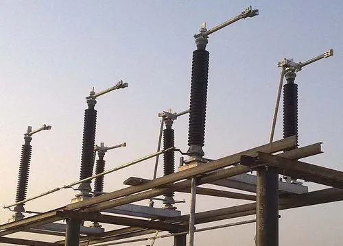
Of all disconnector types, the pantograph disconnector design is the most compact. The application of pantograph disconnectors is especially useful for providing a connection between busbars arranged at two different vertical levels. Due to their compactness, electric trains also use the pantograph design to connect the train to high-voltage overhead lines.
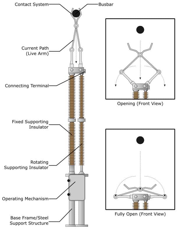
With a pantograph disconnector design, the equivalent current carrying live blade/arm is provided by a scissor-type arrangement consisting of four telescopic booms with moving contacts; the corresponding jaw is a stirrup-type fixture attached to the overhead line/bus. The pantograph mechanism is installed on the support insulator and transfers movement from the rotating insulator to the arms of the pantograph. The two scissor arms provide parallel electrical connections, rather than the single electrical connecting arms that other disconnector types use; this setup lowers circuit resistance.

Pantograph disconnectors involve vertical movement of contact arms and therefore require less separation between phases and thereby help in reduction in substation area. These types of disconnectors are used as bus disconnectors and commonly used with strung bus arrangements and are mostly used at 400 kV level & above.
Knee Type
The knee-type disconnector consists of one articulated arm which, by moving “horizontally” on the plane of the insulators, closes the circuit on a fixed contact located on the side insulator. Since the movement of the arm takes place on the same plane as that of the insulators, the phase-to-phase spacing is minimized.

EARTH SWITCH
Earth switch is a very important equipment for the safety of humans. In the case of double circuit lines, the earthing switches shall be required for earthing the switching inductive currents (electromagnetically induced) and capacitive currents (electrostatically induced) resulting from the energized parallel circuit running parallel to the transmission line.
Earthing switches are assembled in the isolator units having arms at the horizontal state and with the rotation of the operating rod it clings on to the clamp of the disconnector which is in the open position, vertically. It has a mechanical interlocking arrangement with the disconnector. If the isolator is in the closed position, the earth switch cannot be closed.
We must put the earth switch in a close position before doing any work on equipment & on the transmission line.
Above 132KV all isolators must have an earth switch as manual earthing can be done up to 132KV level. However, all line disconnectors must have an earth switch.
Maintenance of Isolators and earth switch
Being a mechanical device, faults are natural to occur in electrical isolators. However, if they receive proper maintenance, these faults can be minimized. Below are some maintenance tips that must be followed to ensure their smooth operation.
- Electrical isolators must be kept clean. They must be clean from salt cement and acid fumes.
- Disconnectors must be replaced with new ones as soon as a defect is observed to prevent the entire circuit.
- The arrangement of contact rods should always be appropriate.
- Alignment of the male-female contacts must be checked and corrected.
- The connections of disconnectors must be tight, and regular inspection must be done to ensure these connections are in place.
- Once the isolator is closed, the earth switch must be closed to check the mechanical interlock of the disconnector.
- Bolts on the clamps must be tightened to prevent any heat signatures from coming into the picture.
- The tightness of the male-female joint must be checked regularly as it can also emit a significant heat signature when loose and checked with a thermal scanner.
- Petroleum jelly can be applied to the rotational elements for smooth operation.
Operation of isolator and earth switch
Both the earth switch and the disconnector can be operated electrically via a motor or manually operated from the switchyard.
It is essential to note that the disconnector is opted for operations at no load. Hence before the operation of the isolator, the operation of the circuit breaker must be checked.
Chopping the loaded line by the operation of the isolator generates a huge arc which can potentially damage the insulation of the disconnector and harm the operator risking an electrocution.
The operation of the earth switch must be done in consultation with the remote substation, as charging of the line from the remote end with the earth switch kept in the closed position on the local end will result in an earth fault and this is often harmful for the weak jumper connection in low voltage lines. This is because the fault clearing time in low-voltage systems is not as low as high voltage substations.
Is a disconnector or Isolator always needed with CB?
Ans: No
In case whenever we have a switchgear panel type electrical installation & use the draw out type CB, then, in this case, the isolation of CB from source & load is achieved due to the draw out type facility available in CB, in this case, the disconnector is not needed with CB.
Whenever CB is fixed type installation for example:
Outdoor switchyard in which a Circuit Breaker is fixed type installed then the draw out of CB is not possible, in this case on both sides of CB, an isolator shall be required to carry out CB maintenance
In GIS type substation in which CB is fixed type then in this case on both sides of CB, a disconnector shall be required to carry out CB maintenance.
Is the disconnector a breaker?
Physically yes, but isolators do not have the arc quenching capabilities which is essential for high-voltage circuit breaking or making.
This article is a part of the Switchgear, where other articles related to switchgear are discussed in details.

