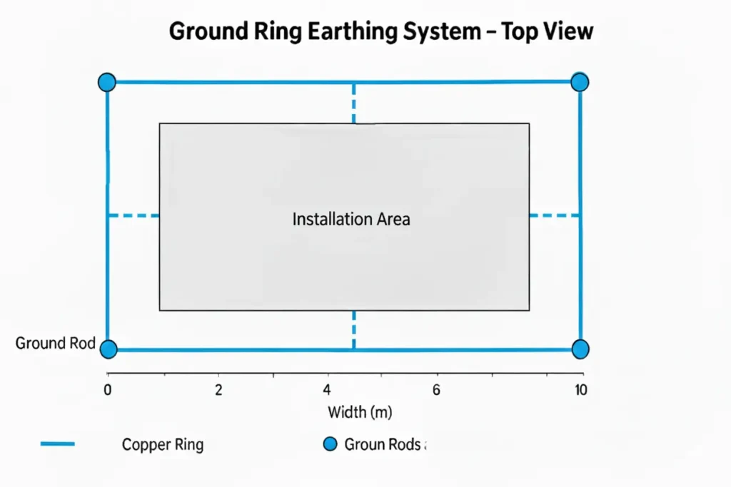
A ground ring electrode is basically a closed loop electrical conductor (mostly copper) buried around the perimeter of an electrical installation like a building, a substation or a equipment area. It forms a continuous low resistant path for the fault current to flow to the earth with uniform grounding potential, enhanced fault current dissipation and reduced dangerous step and touch potential.
The ground ring electrode forms a continuous loop of buried conductor around a structure which provides multiple grounding paths and the current dissipation area also becomes wider. It reduces the localised grounding resistance providing multiple paths for the current to flow, which increases the reliability, even if one section is damaged.
NB: It may be noted that circulating current exist whenever there is a parallel path for current exists with a voltage difference. Ground ring electrodes although have parallel paths but also maintains equipotential surfaces nullifying any circulating current.
Table of Contents
Construction
Conductor: Ground ring electrodes typically uses bare copper conductor because of excellent conductivity, corrosion resistance and its long term stability in the soil. Common size of the conductor varies from 70 mm2 to 120 mm2 (1 AWG to 4 AWG) depending in the fault levels of the installation.
The conductor is sized from the IEEE-80 standard’s adiabatic heating equation,
S = I x √t / k,
Where S is the cross sectional area of the conductor in mm2, I is the fault current in A, t is the fault clearing time in seconds and k is the constant of conductor material.
Example: Considering the fault current as 15 KA and fault clearing time as 1 seconds, k = 205 A.s1/2/mm2.
The minimum diameter of the conductor considering thermal limit is S = 15000 x √1 / 205 =73.17 mm2. But this is only the thermal minimum. After applying the derating factors for corrosion which is 1.2 for benign soil and copper and 2 for highly corrosive soil, mechanical strength factor (1.25 to 2), surge (lightning) factor (1.5 to 3)
Applying the factors the size becomes = 1.5 x 1.5 x 2 x 73.17 = 329.26 mm2. It may be noted that the calculation is done considering the worst case scenerio, in practice the derating fator is considered approximately 2 not 4.5 as in this calculation.
Now for safely grounding 15KA current via a single ground ring electrode, we would need approximately 350 mm2 copper conductor, but in high voltage substations, the ground ring electrodes are parallely connected in various numbers as per the size of the substation depending on the soil resistivity. The closest nearest practical size is 70 mm2 and 350/70 = 5 approximate number of electrodes will be needed to ground 15 KA of current. Typical sizes of conductors are
| Application | Sizes |
| Small Substation | 50-70 mm2 |
| 132KV to 220 KV substation | 95-120 mm2 |
| Extra high voltage substations | 120-185 mm2 |
70 -120 mm2 is taken to be common practical size which can
- Withstand high fault current thermally,
- Provide the mechanical robustness,
- Offers long term corrosion resistance.
Closed loop arrangement: The ground ring electrode is installed as a continuous closed loop, circling the entire building or substation boundary as discussed above. This is done because it ensures uniform ground potential with consistent conductive path. The closed geometry improves the current dissipation through several parallel paths, preventing localized hotspots. This enhances the protection from lightning surges and internal fault currents as well.

Burial depth: The ground ring electrodes are buried usually 0.5 to 0.8 meters deep so that it lies below the frost line and sets to stable moisture level, which aids in the good conductivity. As per studies conducted by the IEEE, the top soil 0.2 to 0.3 m has the worst conductivity as it dries out and loses the ionic transfer capability. At 0.5 to 0.8 meters, moisture being stable lowers the resistivity, provides minimal seasonal variation and improves the overall grounding resistance. At this burial depth, the conductor gets mechanical restraint, thermal buffering and stable positioning by the soil above, this prevents any displacement at higher fault current levels.
If the burial depth is shallow at around 0.3 m, the electromagnetic coupling to control and SCADA cable will increase, risking mis operations. At 0.5 to 0.8 m, the inductive coupling is lowered significantly because the magnetic field intensity decays with the distance (∝ 1/r). The risk of corrosion also decreases at this depth as oxygen diffusion is lower.
Earth rod and grounding grid connection: The ground ring electrode is interconnected to the vertical earth rods at regular intervals for increasing the effective grounding area. Also, it connects to the grounding grid for creation of equipotential multiple parallel path for the fault current to dissipate. These interconnections reduce the earth resistance and ensures reliability even if a section gets damaged.
Bonding with metallic structures: The structural steel columns and equipment frames are bonded directly to the ground ring electrode to maintain a reference potential cross the facility. This eliminates dangerous potential difference between two metal parts, while ensuring safe dissipation of lightning current and integrates the entire structure in to a single low impedance grounding system.
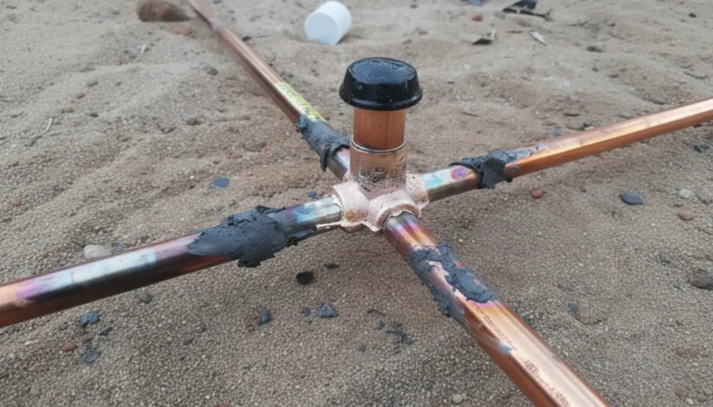
Exothermic welding or compression lugs: For providing a permanent, low resistance connection in the grounding system, exothermic welding is used. This type of welding provides a permanent bond at the molecular level between the conductors unlike other welding processes. The resistance of the welded part is mostly lower than the resistance of the conductor itself, with corrosion proof property and remains unaffected to vibrations.

Compression lugs are also used in grounding as it offers a strong, reliable, and gas tight mechanical connection between the ground ring electrode and the equipment terminals. This connection is easier to install and faster than the exothermic welding, specially indoor and at elevated location, where welding becomes impractical. Compression lugs require no gas flames or chemical reaction, only needs a crimping tool which provides high mechanical pull strength.
Standards
National Electrical Code (NEC): NEC 250.52(A)(4) recognises the ground ring electrode formed by the bare copper conductor which encircles the building or structure. The minimum size of the conductor as per the standard is 2 AWG, buried in direct contact with the earth. The ring must have a mandatory close loop and be a part of the grounding system of the installation, bonded to other electrodes.
IEEE 80 Recommendation: IEEE 80 recommends the use of ground ring electrode and meshes around substation and high exposure facilities for controlling step and touch voltages. The standard emphasises on the perimeter grounding, forming multiple parallel paths, with interconnections between vertical earth rods for maintaining low impedance for the fault current.
IS 3043: IS 3043 advises the installation of perimeter ground conductor around the substation building or equipment for stabilizing ground potential. The ring has to be buried at uniform depth with interconnection with the vertical rod and bonded to metallic structures. Perimeter earthing enhances the lightning dissipation and reduces the step and touch voltages with uniform grounding across the boundary of the facility.
Application
Ground ring electrodes must be chosen for grounding system in:
- Areas with high exposure to lightning such as tall buildings and communication tower.
- Facilities where a strict touch and step voltage control is required, like GIS yard, power plant, AIS switch yard.
- Areas where uniform grounding potential is required like control building, data center, relay house.
- Sites with high soil resistivity as a single rod wont achieve acceptable resistance ground ring electrode will help to reduce the overall system impedance.
- Areas with large perimeter installations like substation, solar farms, battery storage yards or industrial areas.
- Areas requiring lightning protection system integration because a connected ground ring electrode with lightning down conductor and metallic structure forms a unified bonding network of equipotential grounding.
- Areas where redundancy and reliability both are needed like critical power infrastructure.
It is not required in
- Small residential and light commercial installation.
- Areas with narrow perimeter and obstructed pavements
- Rocky terrains where trenching is not possible
- Sites requiring only basic fault protection.
- Sites with extremely corrosive soil with no protective measures.
- Temporary installation and projects with tight budgets.
This article is a part of the Safety and Earthing page, where other articles related to topic are discussed in details.

