Electrode grounding is the method of connecting an electrical installation to the ground using a buried electrode, which can be a rod, plate, pipe or ground ring, for safely dissipating large fault currents. The main purpose of the electrode grounding is to safely dispose off the fault current, lightning surge, switching transients and leakage currents into the soil, which prevents the equipment damage and reduces the shock hazard. Electrode grounding is widely used in substation, transmission towers, diesel generators and other renewable energy systems as it help attain system stability, ensuring equal potential in all surface, thus ensuring the safety of personnel as well as equipment.
Table of Contents
Component of electrode grounding system
Grounding electrode: In the electrode grounding system, the electrode is the primary metal element, which is buried in the soil for discharging the fault current and lightning currents in the system to the earth. Common types of grounding electrode includes, galvanized iron or cast-iron pipes, copper bonded rods, mild steel or galvanized iron plates and copper strips. The selection of the type of electrode depends on the soil resistivity, space of installation and fault current levels. The efficiency of this electrode grounding determines the overall grounding resistance of the grounding system.
Earth pit: It is the enclosure, which houses the grounding electrode in it. The earth pit provides the space for the backfill compounds and ensures moisture retention around the electrode grounding. The earth pit allows for safe inspection of the electrode grounding and resistance testing. The earth pit is constructed with brick, concrete or pre-fabricated chamber for enhanced durability, protection and long term stability of the grounding system. The size of the pit varies from 0.6 x 0.6 m for normal soil with rod or pipe electrode, while 1 x 1 m for plate electrode.
As per industry practice,
| Electrode Type | Soil Condition | Recommended Pit Size |
| Rod/pipe electrode | Normal soil | 0.6 m × 0.6 m |
| Rod/pipe electrode | High resistivity | 0.75 m × 0.75 m |
| Plate electrode (600 × 600 mm) | Any soil | 1 m × 1 m |
| Plate electrode (900 × 900 mm) | Hard soil | 1.2 m × 1.2 m |
| Chemical electrode | Standard | 0.6 m × 0.6 m |
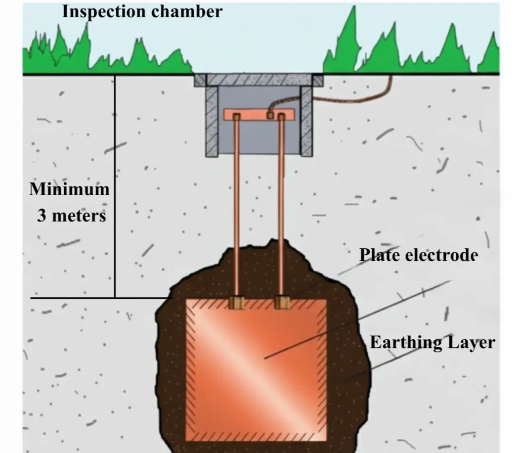
Backfill compound: The backfill compounds used in the electrode grounding reduces the resistivity of the soil around the electrode. After excavation of the earth pit and placement of the electrode, earthing layers are placed which is composed of backfill compounds like charcoal, layer of charcoal and salt, bentonite clay layer and Marconite layer. Charcoal and salt enhances the conductivity but it degrades with time and salt charging can accelerate the corrosion of the electrode. Bentonite layer placed below the top soil, enhances the moisture retension providing stable conductivity across seasons. Proper use of backfilling compounds ensures consistent grounding performance even in harsh soil conditions.
Grounding conductor: The grounding conductor or riser connects the buried grounding electrode to the equipment or building grounding network. The grounding conductor is typically made of copper or galvanised iron strips (high fault current), wires or cables (low fault current). The grounding conductor must be mechanically strong and corrosion resistant and sized to handle the maximum fault current of the system. It is basically the visible link between the buried grounding electrode and the earthing network.
Grounding bus: The earth bus or grounding bus is a common bar that connects multiple earthing connection to a single point. It helps in the orderly bonding of equipment, panels and structures. It improves the rounding layout with reduction in clutter and conductor runs, while providing a low impedance and reliable connection point. The grounding bus is typically made from copper or galvanized iron sized with respect to maximum fault current, allowable temperature rise, and corrosion aspects.
Types of electrode grounding:
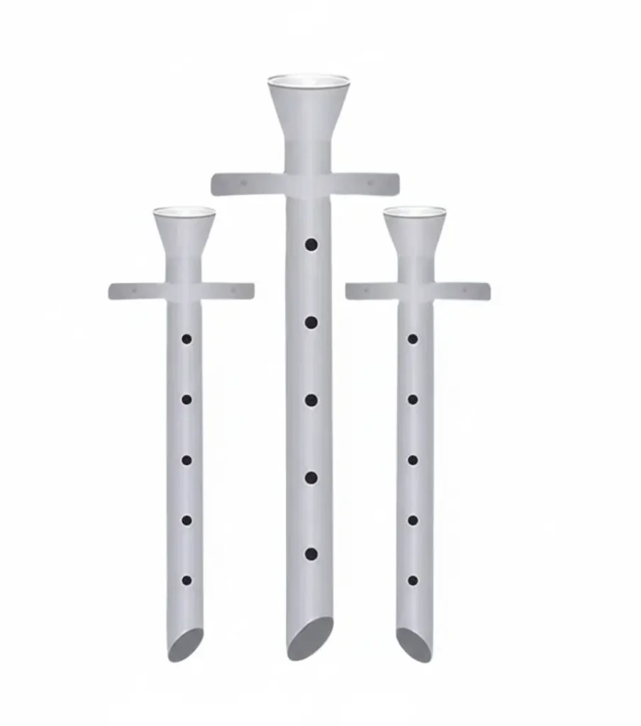
Pipes: Pipe electrode are hollow cast iron, galvanised iron or copper pipes driven vertically in excavated earth pit in order to achieve low grounding resistance. The pipe contains perforations to improve the moisture contact and enhance the soil conductivity around the electrode by allowing entry to the backfill compounds. 12mm dia holes are drilled at every 75 mm spacing is a standard industry practice. This type of electrode grounding is suitable for areas with high water table.

The length of the pipe varies depending upon the resistivity of the soil from a minimum of 2 meters, extending even up to 6 meters using threaded couplers. Cast iron pipes of not less than 100 mm diameter with wall thickness of 13mm (1/2 inch) can be used alternatively mild steel or GI pipes of diameter 38 to 50 mm can be used. The thickness of the pipes (GI/Copper/Mild steel) used in this type of electrode grounding must be more than 1.6 mm.
Rod: Rods are solid cylindrical conductors used as grounding electrodes driven vertically in to the soil using sledge or power hammer to achieve low resistance earthing. These rods are widely used in grounding application of substation, transmission tower and lightning protection system. The threaded design in the rods allow multiple rod coupling to reach the low resistive substrata of the soil at greater depths.
These electrode offers high current handling capability with long service life and excellent resistance to corrosion with copper bonding. The standard diameter of the rod electrode is around 12 to 25 mm with a length of 1.2 to 3 m. The plating thickness for copper bonded rods are 250 to 254 μm while for heavy duty rods are around 350 to 400 μm.
The formula for calculating the resistance of Rod and Pipe electrode is given by
R = ρ/ 2πL [ln (4L/d)-1], where
- R = resistance of the electrode in (Ω)
- Ρ is the soil resistivity in (Ω·m)
- L is the length of the rod in (m)
- d is the diameter of the rod in (m)
Example: A 16 mm dia copper bonded rod with 3 m length and soil resistivity of 100 Ω·m will have a resistance of R = 100/ 2π3 [ln (4×3/.016)-1] = 18.5 Ω.
In order to achieve a grounding resistance of 1 Ω, number of rods required is given by IEEE-80 formula of derating factor for mutual inductance
Rn = R1 / n x F, where R1 is the single rod resistance, n is the number of rods and F is the spacing factor.
The value of F varies from 0.6 to 0.95
- If the spacing between rod is equal to length of the rod, F= 0.85,
- If the spacing between rod is equal to twice the rod length, F= 0.95,
- If the spacing between rod is less than the rod length, F= 0.6 – 0.7.
In order to achieve 1 Ω resistance, with spacing between rods equal to rod length, set the Rn = 1 Ω, using the above formula,
1= 18.5/n x 0.85
Therefore, n = 21.8 = 22, the number of rod electrode needed is 22.
Plate electrode: A plate grounding electrode is basically a galvanized iron or copper plate with a common size of 600 x 600 mm or 900 x 900 mm is buried vertically in a excavated pit where driving deep is not possible because of rocky terrain and other space restrictions. The typical thickness for the copper plates and GI plates must not be less than 3.15 mm and 6mm respectively.

The plates have a large contact interface with the soil, which improves the fault current dissipation factor. Although it is labour intensive, requiring large excavation, it is widely used in industrial and residential grounding. The plate grounding electrodes have a typical depth of 3 to 3.5 m measured from the top edge.
The resistance of plate earthing is given by R = ρ/4a + ρ/2πa ln(2h/a),
where a is the side length of the square plate and ρ is the soil resistivity and h is the buried depth.
Strip or bar: Strip or bar electrode grounding is a horizontally laid electrode, typically made of galvanised iron strips or flat bars, buried at a depth of 0.5 to 1m. It is used in areas where vertical grounding electrodes cannot be driven, such as rocky and densely built-up area. The strips offers a long surface contact with the soil, improving the fault dissipation. Although it requires more trenching works, these grounding electrodes proves to be highly effective for large area grounding systems where, soil condition prevents vertical installations of grounding electrode.
Although, strip electrode grounding are extensively used in construction of the grounding grid of substations, solar plants and industrial switchyards, which provides equipotential bonding, but strips alone cannot provide the low resistance required in the substations Hence, rod electrode grounding are used in combination to effectively reduce the earth resistance. Typical size of GI strips are 50 mm x 6 mm or 75 mm x 10 mm and for copper strips 25 mm x 3 mm to 50 mm x 6 mm.
Installation process in electrode grounding
- Firstly, a low resistive soil has to be chosen for the grounding.
- Then excavation of the earth pit has to be done till the required depth is reached.
- After the excavation is completed, we have to place the electrode either vertically or horizontally depending up on the type.
- Fill up the excavated pit using earthing layer and backfill compounds with compacting sequentially and watering.
- Connect the earth riser with the grounding conductor by welding or clamping.
- Construct the inspection chamber with concrete or brick masonry works.
- Label the earth pit and close the inspection chamber.
This article is a part of the Safety and Earthing page, where other articles related to topic are discussed in details.

