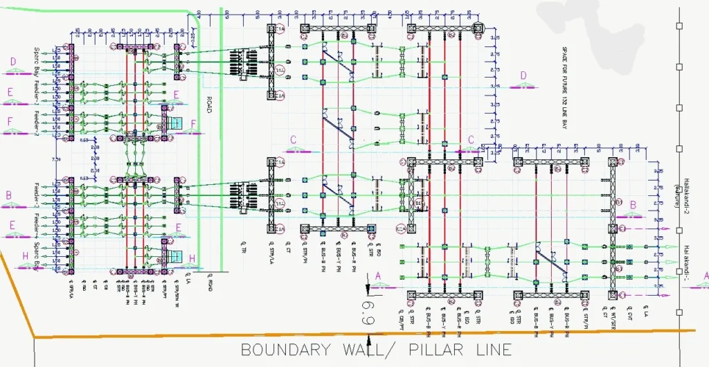
Substation Layout is basically an orderly arrangement of electrical equipment based on function, safety, and security, considering several clearances and space constraints or availability of land for achieving better operational flexibility, security of power supply, maintenance flexibility, along with accounting for lower cost.

A well-designed Substation layout offers safety of equipment and personnel during operation and maintenance, efficient design offers security to power flow by not obstructing the flow due to shutdown or malfunction in a transmission element.
Table of Contents
Types of Substation based on Layout
AIS or Air Insulated Substation: In this substation layout, the primary electrical insulation used is air; this type of substation requires a large area as the electrical clearance involved is greater. However, this type of substation is cheaper, involves low initial cost, is easy to expand based on load demand, and is also simple to maintain. This type of substation is best suited for rural and semi-urban areas, where land is cheap, easily available, and with minimal right-of-way issues.
GIS or Gas Insulated Substation: In a GIS substation layout, sulphur hexafluoride gas is extensively used as the electrical insulating medium. The entire substation bay equipment, be it busbar, isolator, or breaker, is arranged inside a metal-clad compartment filled with SF6 gas, which makes the system compact. Because of this, the land area requirement is minimal compared to the AIS of the same specification, approximately 70% less. Although it has a higher initial cost, the maintenance cost is lower because it is highly reliable and requires less maintenance. These are best suited for urban
Hybrid Substation: A hybrid substation includes the best of both AIS and GIS substation. It involves GIS modules for the critical bay such as incoming and outgoing feeders and incorporates an AIS system for simple bays like transformers. It is a flexible design for sites with various constraints. Use of hybrid design philosophy optimizes land requirements as well the cost associated. It provides better reliability than AIS alone and easier expansion compared to GIS substations.
Factors affecting Substation layout
Voltage level: The Voltage level becomes the main factor that affects the substation layout, because the electrical insulation is directly dependent on the voltage, and hence it impacts the size of the electrical equipment. Also, the electrical clearances are a direct function of the voltage level, hence in the substation layout, bay width and length is determined after fixation of the voltage level.
| SUBSTATION VOLTAGE LEVELS | LAND REQUIREMENT |
| 765/400/220 KV | 100 to 120 Acres |
| 400/220/132 KV | 45 to 60 Acres |
| 220/132/33 KV | 15 to 18 Acres |
| 132/33/11 KV | 8 to 10 Acres |
| 33/11 KV | 2-3 Acres |
Availability of Land: The layout of a substation depends upon the geography and land availability in that area. As in urban areas, land is less available and hence GIS layout is best suited, whereas in rural areas, AIS layouts are planned. The type of soil determines the substation earthing; rocky terrains also require special foundation designs. Flood-affected or low-lying areas require a planned elevated switchyard higher than the highest flood level last recorded.
Number of feeders and transformers: If the number of feeders are more, the layout area will be more. Transformers that are majorly oil-filled require a safe distance between them, which can be effectively minimized by introducing a firewall between them. The number of transformers also directly impacts the area of the layout, each requiring two separate bays.

Safety requirements: The substation layout must provide a safe environment for operational and maintenance personnel as well as for equipment. This is ensured by maintaining proper electrical clearances, proper earth mat design for limiting step and touch voltages. Safety must also be ensured for oil-filled transformers by installing a firewall, an oil soak pit, and fire hydrant systems. Boundary walls and fencing of the switchyard must be proper in the layout to ensure authorized personnel entry only.
Future expansion: Considering the growth of the load in the future, the layout must incorporate space for an additional bay for future expansion, as well as transmission and distribution corridors.
Optimization of cost: Substation layout design involves a trade-off between reliability, cost, and safety. The cost can be optimized by proper utilization of the land area, selection of a proper busbar arrangement that enhances the reliability of the system, and incorporating energy-efficient equipment.
Main components considered in a Substation Layout
Power Transformer: Power Transformers are the major equipment in the substation that is responsible for stepping up or down the voltage level. It is usually placed near the busbars for shorter connections. For fire safety, the minimum space requirements must be there between two oil-filled transformers, which depend on oil volume and voltage levels. Oil-filled transformers must have soak pits and a hydrant system.
Circuit Breaker: These help in interrupting and making a high-voltage circuit safe. The circuit breakers must be placed in all bays incommer or transformer, to interrupt the circuit when required. It must have isolators on both sides to promote maintenance when required by switching the isolators open.
Isolators: Isolators help in disconnecting an unloaded circuit, for manual isolation of equipment during maintenance. It must be operated after the circuit breaker operates. Isolators are of various types: horizontal break, vertical break, center break, pantograph type, each providing unique space requirements.
| TYPE | SPACE REQUIREMENT | VOLTAGE RANGE |
| Horizontal Break | More Horizontal space | 33 to 220 KV |
| Vertical Break | More Vertical space | 66 to 400 KV |
| Center Break | Moderate space | 66 to 400 KV |
| Pantograph | Minimum Horizontal Space | 220 to 765 KV |
Current Transformer: This provides the proportionally lowered current input to various relays for protection and meters for metering purposes, also it provides inputs to the BCU indirectly to the SCADA system. These are installed on feeder bays or transformers near to Circuit breakers.
Potential Transformers: This provides the proportionally lowered voltage inputs to various relays for protection and meters for metering purposes also, it provides inputs to the BCU indirectly to the SCADA system. They are installed in a separate bay.
Capacitive Voltage Transformers: CVTs on the other hand, are installed in the incommer end, which are also capable of sending proportionally lowered voltage inputs similar to a potential transformer.
Lightning Arresters: This protects the other substation equipment from lightning surges and also traveling switching surges. Hence, they are installed as the first equipment at the entry of any lines in the substation, also installed near the transformers at both HV and LV sides for increased protection.
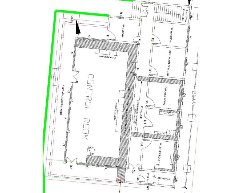
Control Room: This is basically the room that houses all the control and relay panels associated with each bay of the substation, metering panels, communication equipment, SCADA system, and battery room housing batteries, with acid-resistant flooring and a charger room. The control room must be centrally located to ensure less cable run, and must be climate-controlled for equipment reliability. It must have a redundant power supply and, fire protection system.


