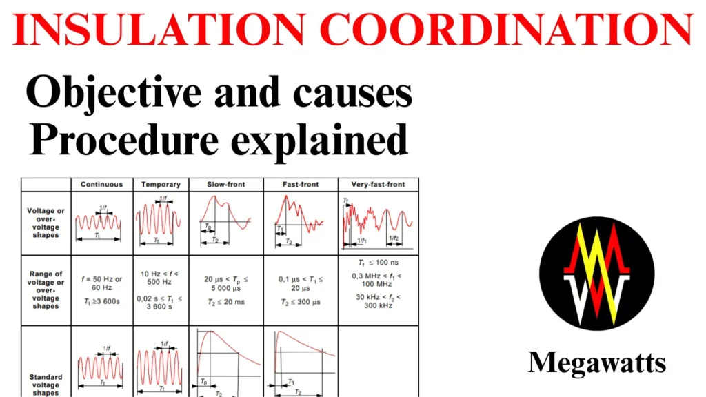
Insulation coordination is basically the selection of the dielectric strength of the equipment with respect to the operating voltage and the overvoltage stress it will be subjected to during the system operation, considering the environment and characteristics of protective devices.

The objective of insulation coordination is to increase the reliability of equipment during operation and ensure human safety. Effective insulation coordination prevents insulation failure during normal and abnormal operating conditions by ensuring the protective devices’ action beforehand. Insulation coordinationis therefore very important in an electric substation for the equipment, transmission line, and transformer as well.
Table of Contents
Overvoltage in the power system
Insulation coordination is required because overvoltage stresses out the insulation and can cause insulation failure. The types of overvoltages are:
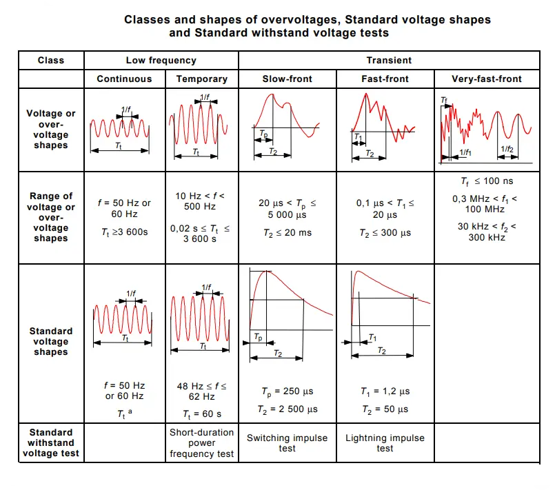
Lightning strikes: When lightning strikes near electrical power systems, an overvoltage surge is observed in the system because of electromagnetic induction. These surges can attain a peak in 1.2 ms and can continue to drop to half of the value in 50 ms. If not discharged through a protective device, it can potentially damage all equipment connected in the switchyard.
Switching Surges: The voltage surge caused by the switching action of the circuit breaker under normal or faulty conditions is called a switching surge. These surges are predominant beyond 220 KV systems.
Temporary overvoltage: The temporary overvoltage surges are short-duration surges that occur due to sudden load rejection or sudden occurrence of an earth fault due to some insulation failure. They can be oscillatory or non-oscillatory and damped.
Hence, Insulation coordination takes into account all the overvoltages that occurs in a power system.
Procedure for Insulation Coordination
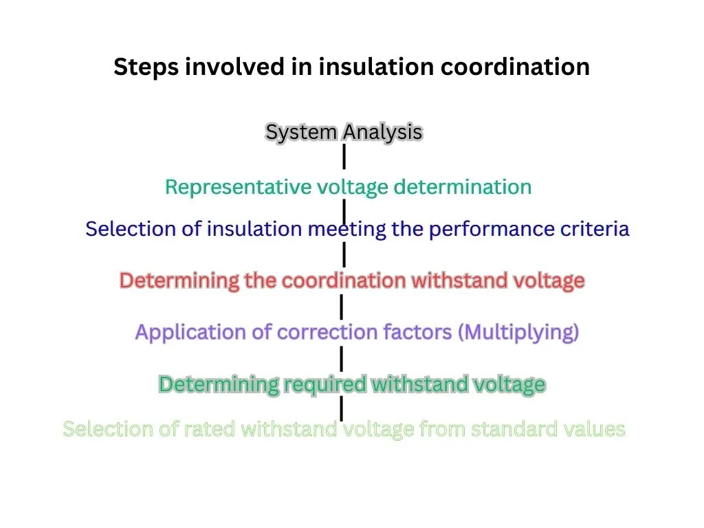
The procedure of insulation coordination basically selects the highest voltage that the equipment can withstand from a set of corresponding standard rated withstand voltages that characterise the insulation requirement for an application.

The standard set of Power frequency withstand voltages for insulation coordination are: 10 KV, 20 KV, 28 KV, 38 KV, 50 KV, 70 KV, 95 KV, 115 KV, 140 KV, 185 KV, 230 KV, 275 KV, 325 KV, 360 KV, 395 KV, 460 KV, 510 KV, 570 KV, 630 KV, 680 KV, 710 KV, 790 KV, 830 KV, 880 KV, 960 KV, 975 KV.
The standard set of peak impulse withstand voltages for insulation coordination are: 20 KV, 40 KV, 60 KV, 75 KV, 95 KV, 125 KV, 145 KV, 170 KV, 200 KV, 250 KV, 325 KV, 380 KV, 450 KV, 550 KV, 650 KV, 750 KV, 850 KV, 950 KV, 1050 KV, 1175 KV, 1300 KV, 1425 KV, 1550 KV, 1675 KV, 1800 KV, 1950 KV, 2100 KV, 2250 KV, 2400 KV.
By system analysis, the voltage and overvoltage that stress the insulation can be found out in terms of amplitude, shape, and duration by considering the protective device. For each class of voltage, the analysis can determine a representative voltage and overvoltage from the table below.

The representative voltage and overvoltage can be assumed to be maximum or a set of peak values.
After the selection of the representative voltage and overvoltage, the coordination withstand voltage is determined, which is the lowest value of withstand voltages of the insulation meeting the performance criteria and service condition.
The coordination withstand voltages are then converted to the required withstand voltage by multiplying several test condition factors, which compensate for the difference between the actual in-service condition of the insulation and from theoretical.
The factors are the atmospheric correction factor Kt and the safety factor Ks, and the altitude correction factor Ka.
The atmospheric correction factor Kt is applicable for external insulation only. It is the factor that differentiates the standard and actual atmospheric conditions. While the safety factor checks the installation quality, equipment assembly, aging of insulation, etc. The altitude correction factor considers the average air pressure present at a specific altitude.
The selection of the rated level of insulation must consist of the most economical standard rated withstand voltage of insulation, which ensures all required withstand voltages are met.
The range of the highest voltage of the equipment
The highest voltages of the equipment are divided into two ranges, they are:
Range 1: 1KV to 245 KV covers the distribution voltage level and transmission voltage levels.
| Highest Voltage for Equipment Um (kV, r.m.s.) | Standard Rated Short-Duration Power-Frequency Withstand Voltage (kV, r.m.s.) | Standard Rated Lightning Impulse Withstand Voltage (kV, peak) |
| 3.6 | 10 | 20/40 |
| 7.2 | 20 | 40/60 |
| 12 | 28 | 60 / 75 / 95 |
| 17.5 | 38 | 75/95 |
| 24 | 50 | 95/125 / 145 |
| 36 | 70 | 145/170 |
| 52 | 95 | 250 |
| 72.5 | 140 | 325 |
| 100 | 150/185 | (380)/450 |
| 123 | 185/230 | (450) / 550 |
| 145 | 185/230/275 | 450/550 / 650 |
| 170 | 230/275/325 | 550/650 / 750 |
| 245 | 275/325/360/395/460 | 650 / 750 / 850 / 950/1050 |
Range 2: Above 245 KV covers the transmission voltage levels.
| Highest Voltage for Equipment Um (kV, r.m.s.) | Longitudinal Insulation (kV, peak) | Phase-to-Earth (kV, peak) | Phase-to-Phase (ratio to phase-to-earth peak) | Standard Rated Lightning Impulse Withstand Voltage (kV, peak) |
| 300ᶜ | 750 | 750 | 1.50 | 850 |
| 950 | ||||
| 750 | 850 | 1.50 | 950 | |
| 1050 | ||||
| 362 | 850 | 850 | 1.50 | 950 |
| 1050 | ||||
| 850 | 950 | 1.50 | 1050 | |
| 1175 | ||||
| 420 | 850 | 850 | 1.60 | 1050 |
| 1175 | ||||
| 950 | 950 | 1.50 | 1175 | |
| 1300 | ||||
| 950 | 1050 | 1.50 | 1300 | |
| 1425 | ||||
| 550 | 950 | 950 | 1.70 | 1175 |
| 1300 | ||||
| 950 | 1050 | 1.60 | 1300 | |
| 1425 | ||||
| 950 1050 | 1175 | 1.50 | 1425 | |
| 1550 | ||||
| 800 | 1175 | 1300 | 1.70 | 1675 |
| 1800 | ||||
| 1175 | 1425 | 1.70 | 1800 | |
| 1950 | ||||
| 1175 1300 | 1550 | 1.60 | 1950 | |
| 2100 |
- For phase-to-phase insulation range 1, the power frequency and lightning impulse phase-to-phase withstand voltage are equal to the relevant phase-to-earth withstand voltages.
- For phase-to-phase insulation range 2, the standard lightning impulse phase-to-phase withstand voltage is equal to the lightning impulse phase-to-earth voltage.
- For longitudinal insulation range 1, the standard power frequency and lightning impulse voltages are equal to the relevant phase-to-earth withstand voltage.
- For longitudinal insulation range 2, the standard switching impulse withstand voltage case, the peak power frequency of opposite polarity is Um * √2 / √3.
- For longitudinal insulation range 2, the standard lightning impulse withstand voltage case, the peak power frequency of opposite polarity is 0.7 * Um * √2 / √3
Two Standard voltage requirement
Basically, only two standard rated withstand voltages are sufficient for determining the rated insulation level of any equipment and insulation coordination.
- For Range 1 Equipment: the standard lightning impulse withstand voltage and short-duration power frequency withstand voltage.
- For Range 2 Equipment: the standard switching impulse withstand voltage and the rated lightning impulse withstand voltage.

