The minimum distance or gap that is required between two conducting parts, without causing any electrical flashover, is known as electrical clearance. Electrical clearance is a function of the implied voltage or potential difference between the two conductors.

If the voltage between two conductors is more, then the required electrical clearance will be higher. In case the gap is less, charges from one conductor will flow to another conductor, making the other one charged as well.
Table of Contents
Electrical clearances are important in a substation for maintaining the safety of personnel, safety of the equipment, and the reliability of the operation.
Types of electrical clearance
Vertical clearance: It is the minimum vertical distance between the charged conductor and the ground, for example the the clearance between the equipment top and the bus bar, charged overhead line, and the tower structures, the gap between the ground wire and the top conductor.
Horizontal clearance: It is the minimum horizontal distance between two charged conductors or between charged conductors and a grounded structure, for example, the phase-to-phase clearance, phase-to-ground clearance, or equipment-to-equipment distance.
Classification of Electrical Clearance based on Function
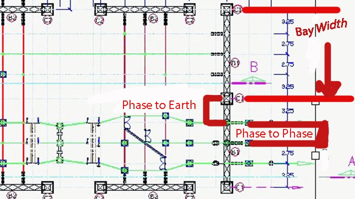
Phase-to-phase clearance: As the different phases incorporate a potential difference between them, reliable operation will cease to exist if they are electrically shorted. Therefore, the phase-to-phase clearance must be maintained. It is a function of system voltage and insulation.

Phase-to-earth clearance: It is the minimum distance from a phase conductor to a grounded structure. In case this minimum distance or gap is not maintained, current may flow to the grounded part, causing an earth fault to exist in the line. If maintained properly, it prevents arcing during normal and faulty conditions.
Sectional Clearance: These are the minimum distances between the equipment, like the Circuit breaker, isolator, current transformer, and busbar, which are essential for safe operation of the equipment, as well as to provide safe working of personnel under the charged condition. The distance between the equipment in any one phase must be higher than the safe phase to earth clearance, and the foundation of the equipment must not overlay.
| Voltage Level | 33KV | 66KV | 132KV | 220KV | 400KV | 800KV |
| Bay WIdth | 5.5 m | 7.6 m | 12 m | 16m | 24 m | 45 m |
| Phase-to-Phase clearance | 0.320 m | 0.630 m | 1.3 m | 2.1 m | 4.2 m | 9.4 m |
| Phase to earth clearance | 0.320 m | 0.630 m | 1.3 m | 2.1 m | 3.5 m | 6.4 m |
| Sectional Clearance | 2.8 m | 3.1 m | 4 m | 5 m | 6.5 m | 10.3 m |
| Equipment Height (Live to Ground) | 3.7 m | 4 m | 4.6 m | 5.5 m | 8 m | 14 m |
| Main Busbar height from Ground | 5.5 m | 6 m | 9 m | 11.7 m | 15 m | 27m |
Height of the lowest portion of the insulator supporting the live conductor, equipment parts, etc, where it meets the earthed metal structure, is 2.440 m for all systems.
The distance between conductors is dependent on the bay width, short circuit forces, and wind swings. It is normally shown on the plan drawing, whereas equipment-to-equipment distance is shown in the sectional elevation.
Electrical clearance is also required when power lines cross each other in order to avoid any flashover or arcing between the power lines of different voltage levels. Also, overhead lines sag because of heat resulting from high current carrying and atmospheric temperature, as well as ice loading. In order to eliminate the risk of contact minimum vertical clearance has to be met.
Minimum electrical clearance between the AC power lines crossing
| System Voltage | 11 to 66 KV | 132 KV | 220 KV | 400 KV | 800 KV |
| 11 to 66 KV | 2.44 m | 3.05 m | 4.58 m | 5.49 m | 7.94 m |
| 132 KV | 3.05 m | 3.05 m | 4.58 m | 5.49 m | 7.94 m |
| 220 KV | 4.58 m | 4.58 m | 4.58 m | 5.49 m | 7.94 m |
| 400 KV | 5.49 m | 5.49 m | 5.49 m | 5.49 m | 7.94 m |
| 800 KV | 7.94 m | 7.94 m | 7.94 m | 7.94 m | 7.94 m |
Minimum electrical clearance between the AC and DC power lines crossing
| System Voltage | 100 KV DC | 200 KV DC | 300 KV DC | 400 KV DC | 500 KV DC | 600 KV DC |
| 11 to 66 KV | 3.05 m | 4.71 m | 5.32 m | 6.04 m | 6.79 m | 7.54 m |
| 132 KV AC | 3.05 m | 4.71 m | 5.32 m | 6.04 m | 6.79 m | 7.54 m |
| 220 KV AC | 4.58 m | 4.71 m | 5.32 m | 6.04 m | 6.79 m | 7.54 m |
| 200 KV DC | 4.71 m | 4.71 m | 5.32 m | 6.04 m | 6.79 m | 7.54 m |
| 400 KV AC | 5.49 m | 5.49 m | 5.49 m | 6.04 m | 6.79 m | 7.54 m |
| 400 KV DC | 6.04 m | 6.04 m | 6.04 m | 6.04 m | 6.79 m | 7.54 m |
| 500 KV DC | 6.79 m | 6.79 m | 6.79 m | 6.79 m | 6.79 m | 7.54 m |
| 600 KV DC | 7.54 m | 7.54 m | 7.54 m | 7.54 m | 7.54 m | 7.54 m |
| 800 KV DC | 7.94 m | 7.94 m | 7.94 m | 7.94 m | 7.94 m | 7.94 m |
Overhead lines crossing buildings:
It is advisable not to start any construction works under an overhead transmission line; however, if it exists, it must be ensured that a vertical clearance of 3.7m minimum exists for lines between 650 Volts to 33 KV. For lines exceeding 33 KV, a vertical clearance of 3.7 m should be maintained, along with 0.3 m for every additional 33KV thereof.
While the horizontal clearance in case of overhead transmission line and buildings should be 1.2 m up to 11KV and 2 m up to 33KV. In case of extra high voltage lines above 33 KV, 0.3 m should be added to the initial clearance of 2 m for every additional 33 KV.
In case of HVDC systems and buildings, the vertical and horizontal clearances must be
| DC Voltage | Vertical clearance | Horizontal clearance |
| 500 KV DC | 9.1 m | 7.4 m |
| 600 KV DC | 10.3 m | 8.6 m |
| 800 KV DC | 12.4 m | 10.7 m |
Electrical clearance on the river crossing must be above 3050 mm above the highest flood level recorded.
Minimum clearance over telecom lines for PTCC clearance must be
| Voltage Level | Minimum clearance |
| 132 KV AC | 2745 mm |
| 220 KV AC | 3050 mm |
| 400 AC | 4880 mm |
Minimum electrical clearance for a Railway crossing
| Voltage Level | Minimum Vertical Clearance under maximum sag of the bottom conductor |
| 33 KV and 66KV | 14.10 m |
| 132 KV | 14,60 m |
| 220 KV | 15.40 m |
| 400 KV | 17,90 m |
| 500 KV | 19.30 m |
| 800 KV | 23.40 m |
This article is a part of the page Substation Guide.

