Table of Contents
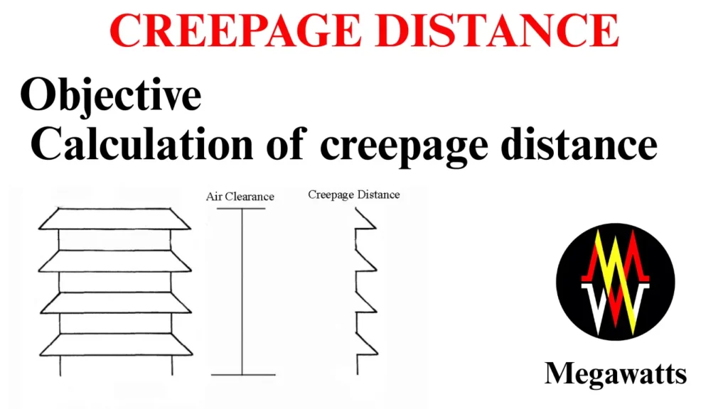
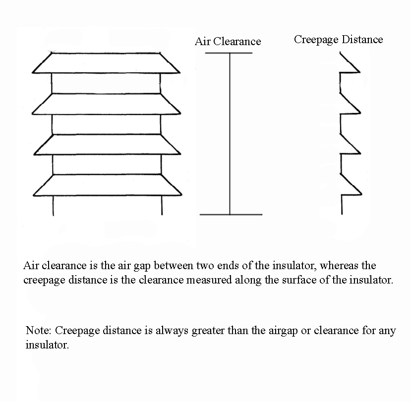
Creepage distance is the minimum distance between two conductors (phase to earth or phase to phase) along the surface of the separating insulator. It is the surface leakage path that the leakage current will take across the insulator via its surface and not through air.

As the path is intended via the surface of the insulator only, it makes creepage different from clearance, which is basically the air gap between two conductors.
Objective of creepage distances
Because of air pollution, in the area of the substation, the insulators often experience the deposition of foreign particles like dust, salts, industrial waste, etc. These particles, mixed with moisture, fog, often become conductive in nature and can potentially conduct the current across the surface of the insulator. Also, with the aging of the insulator, there is a change in its properties; if the creepage distance is not maintained, leakage current will flow across the insulator, causing a flashover.
In order to find the specific creepage gap, certain dimensional aspects of the insulator must be taken into consideration. These aspects are basically the shape of the shed and the profile of the insulator. The diameter and the position also play a role.
Factors influening creepage distance of insulator
Profile of insulator
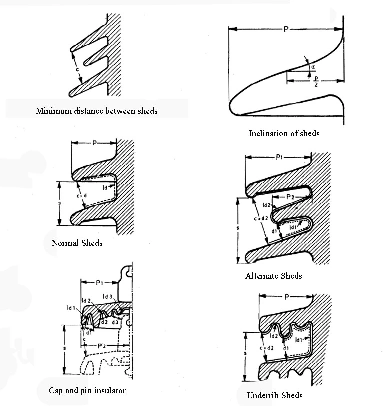
The profile of an insulator is characterised by
The minimum distance between sheds: It ensures that rainwater and dust do not form a conductive layer on the surface of the insulator. Typical values are 40 to 60 mm for porcelain or glass insulators and 25 to 45mm for polymer insulators.
Ratio of the space between sheds and overhang (p/h): It directly affects the creepage gap of an insulator and its self-cleaning ability. The IEC recommendation for insulator design is 0.7≤ p/h ≤1.0. If the ratio is less than 0.7, the sheds will be very close to each other, and there will be a risk of bridging the leakage current by water and pollution.
If the ratio is more than 1, the sheds will be far apart, which means the number of sheds will be less per unit height of insulator, indirectly making the creepage distance less. For porcelain and glass insulators, the ratio is optimum between 0.8 to 1. For polymer insulator0.7 to 0.9 serves best because of the hydrophobicity of the polymer insulator. In very high pollution zones, p/h can be even lowered to increase the creepage distance.
Inclination of the shed: The inclination of the shed or shed angle is another important design factor, which determines how quickly the rainwater will drain from the insulator, creating a dry area. It promotes creation of dry zone, self cleaning as the pollution and dust will be washed away, prevents water film formation on the surface of the insulator. IEC recommendation is 10 to 30 degrees. For porcelain and glass 20 degree is the usual practice, the composite polymer insulator can make use of smaller angle between 10 to 15 degrees because of their hydrophobicity property.
Creepage Factor: Ratio of creepage distance and air clearance, which shows how long the creepage distance is compared to air clearance. The higher the value of the creepage factor better the performance of the insulator under pollution. Typical value of the creepage factor is 2.5 to 4 for post insulators and suspension disc insulator strings.

Profile Factor: It is the ratio of the protected creepage distance that is sheltered from rain via the overhang sheds to the total creepage distance. It indicates how well the part of the insulator is kept dry and clean by the contours. A higher value of the profile factor means better performance of the insulator during rain and pollution. A well-designed insulator has a profile factor ranging from 0.60 to 0.85.
Average Diameter: Many lab tests infer that the post and hollow insulators in polluted areas perform poorly with an increase in average diameter. Therefore, a correction factor, Kd is introduced in the calculation of creepage distance.
For average diameter Dm < 300 mm, Kd =1,
for 300< Dm < 500 mm, Kd =1.1 and
for Dm > 500mm, Kd = 1.2
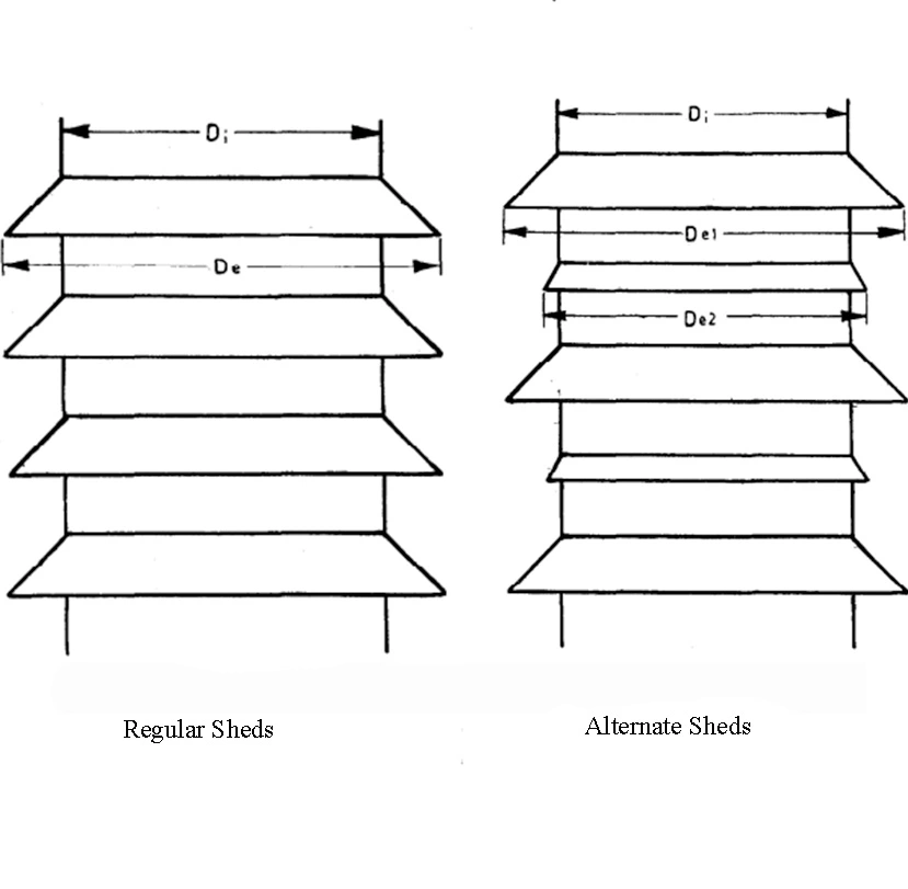
For the average profile of an insulator, the average diameter Dm is given by the formula,
![]()
Where, lt is the total creepage distance of the insulator,
D(I) is the diameter at the creepage distance I, measured from one electrode.
The above formula may be approximated in simple relations
For insulator with regular sheds,
![]()

For insulator with alternate sheds,
![]()
Pollution Levels
| Pollution Level | Environment |
| Light | Areas without industries and with low density housesAreas with low density industries with frequent rainfallAgricultural areasMountain areasAreas which are atleast 15-20 km far from sea and not getting sea winds. |
| Medium | Areas with industries not producing polluting smokes.Areas with high density houses/industries with frequent rainfall.Areas getting sea wind but far away from the sea. |
| Heavy | Areas with high density industries or suburban areas of big cities.Areas close to sea and exposed to strong sea wind. |
| Very Heavy | Areas subjected to conductive dust and industrial smoke.Areas near sea coast exposed to sea spray.Desert areas with no rain and strong winds of salt and sand with regular condensation. |
| Notes: Use of fertilizer spray and burning of crops residue can lead to high pollution levels Distance from sea depends on topography and wind speed and direction. | |
Minimum specific creepage distance
| Pollution level | Minimum specific creepage distance (mm/KV) |
| Light | 16 mm/KV |
| Medium | 20 mm/KV |
| Heavy | 25 mm/KV |
| Very Heavy | 31 mm/KV |
| Note: (i) For actual creepage distance, manufacturing tolerances are applicable. (ii) Ratio of leakage distance is measured between phase to earth and phase to phase of the highest system voltage. (iii) For areas with very light pollution levels 12 mm/KV can also be chosen. (iv) For areas with very high level of pollution, specific creepage distance can be taken higher than 31 mm/KV, based on lab results or service experience. | |
Determination of Creepage distance
The minimum creepage distance of an insulator between phase to earth is calculated based on the pollution level at the site by the relation:
Minimum creepage distance = Minimum specific creepage distance based on pollution level * highest system voltage phase to phase * correction factor (Kd)
If the insulator is used between phase to phase spacer then the minimum creepage distance must be multiplied by 1.732 for 3-phase system.

