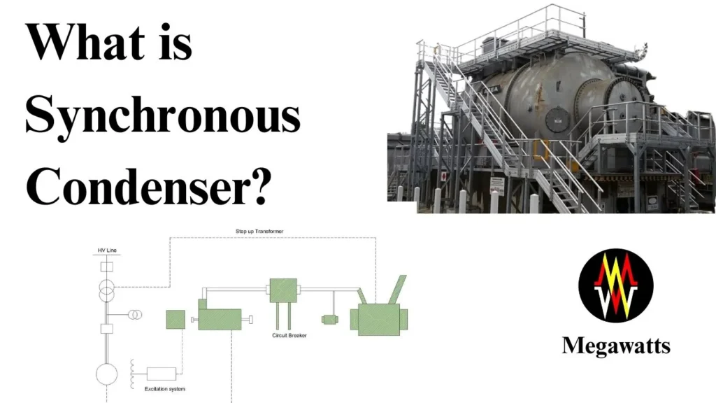
A synchronous condenser is an electrical machine, used in the substations for absorbing or supplying reactive power by controlling the excitation of the machine, thus making the grid stable and also regulate the voltage levels.
Table of Contents
Working Principle of synchronous condenser
The synchronous condenser works like a synchronous motor without any mechanical load attached to it. It has a stator, three-phase connected which produces the rotating magnetic field. The rotor houses the DC field winding which produces constant magnetic field, south and north poles on the rotor. The rotor can be salient type or cylindrical type.
When the AC is supplied to the stator winding, it produces the rotating magnetic field at a synchronous speed.
Ns = 120 f/P, where f is the supply frequency and P is the number of poles.
DC is supplied to the field winding of the rotor via a brushless excitation system or slip rings which generates fixed south and north poles on the rotor. At, a standstill position, the rotating magnetic field of the stator fails to take the rotor along with it, thus only creating a push-and-pull effect on the rotor.
But as the rotor is brought to synchronous speed via auxiliary motor or VFD, the constant magnetic field of the rotor locks onto the rotating magnetic field of the stator as the north pole on the rotor locks onto the south pole of the stator and vice-versa, thus the rotor keeps moving at synchronous speed with the auxiliary motor disengaged. It may be noted that there is no slip between the stator and rotor once the lock-in is established.
Now if the current and voltage are in phase, the synchronous condenser rotates at synchronous speed only absorbing some power to compensate for the losses in it which is minimal.
But when the current starts to lag behind the voltage in the system because of increased inductive load, the power factor drops. Now to counter this, the synchronous condenser is made to supply the reactive power by increasing the DC field current, thus acting as a capacitor where the current leads the voltage. This supply of leading reactive power cancels out the lagging reactive power and thus the power factor of the system improves along with the voltage.
In the case of the system having a leading power factor, where current is leading the voltage, the synchronous condenser is made to absorb the reactive power by restricting the DC field current, it makes the synchronous condenser act as an inductor where current lags the voltage, this absorption of reactive power from the system helps to improve the power factor of the system while keeping voltage within the normal range.
Major Components of a Synchronous Condenser
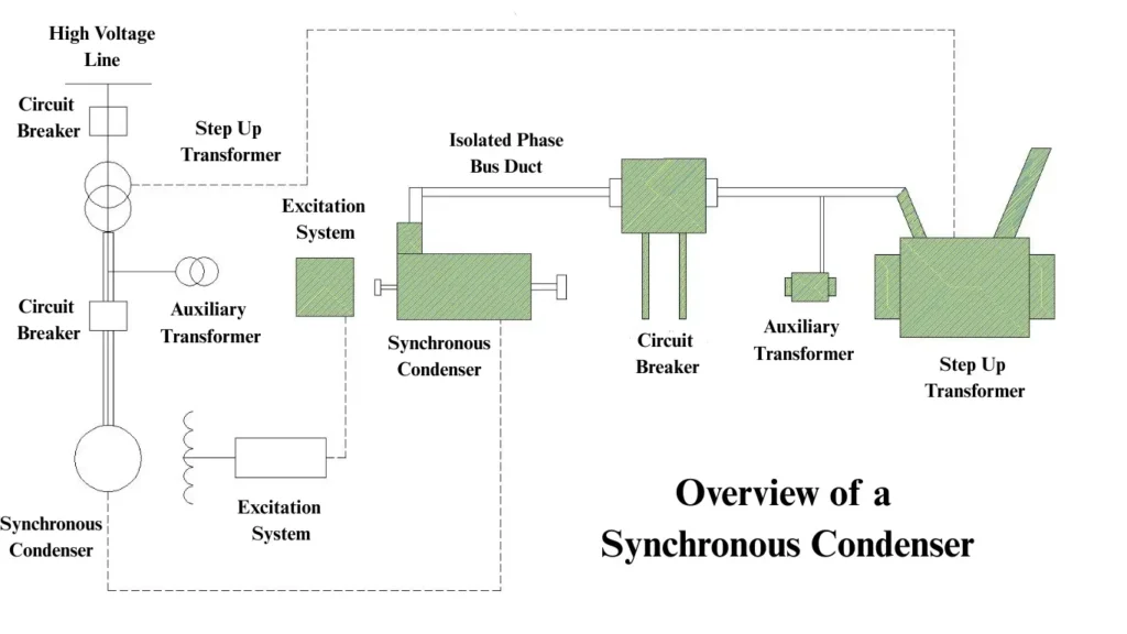
Synchronous motor: The synchronous motor operates with no mechanical load, connected to the grid via a step-up transformer as its terminal voltage is between 11-30 KV. It is capable of absorbing and supplying reactive power by the control of its field excitation.

Cooling systems: The cooling system is used for removing heat from the windings and bearings of the machine which is developed because of iron loss, hysteresis losses, and mechanical windage. Machines conventionally up to 200 MVA ratings are air-cooled, however from 200-700 MVA rating machines are hydrogen-cooled. Higher-rated machines employ both hydrogen cooling and water cooling for the removal of heat.
Excitation system: This supplies the DC current to the field winding of the machine. It is so designed that a critical value is worked out where little stator current is drawn from the system to counter the losses at the unity power factor. When the field current is lower than the critical value, the machine becomes under-excited and absorbs reactive power. When the field current is above the critical value, the machine becomes overexcited and supplies reactive power. It can be noted that the supply of reactive power is limited by the thermal limit of the rotor and absorption is limited by the thermal limits of the stator core.
Lube oil system: This is typically used for the lubrication of the rotor bearings so that the rotation of the rotor is smooth with minimum frictional resistance. Large lube oil system includes oil filters, oil pumps, oil sumps, and oil coolers.
Step-up transformer: Most of the synchronous condensers have a terminal voltage of 11-30 KV. Hence it requires a step-up transformer to match the system voltage at the grid side. The impedance of the transformer significantly affects the VAR supply and absorption of the synchronous machine.
As the synchronous condenser supplies reactive power, the current passes through the transformer’s impedance and causes a voltage drop. This voltage drop lowers the effective voltage in the condenser’s terminal. If this voltage drop becomes significant because of high transformer impedance, the supply of reactive power will become limited.
Auxiliary Transformer: An auxiliary transformer is required for the synchronous condensers for supplying the auxiliary loads like control panels, oil pumps, fans, excitation, etc. It is a step-down transformer that lowers the grid voltage to 440 volts or so for the supply at low voltages.
Starting mechanism
Pony motor with VFD: A pony motor is a small motor that is capable of bringing the rotor of the condenser to synchronous speed. It starts with the input from VFD at low frequency and voltage attains slow rotational speed. The VFD increases the frequency and the rotor speed increases to near synchronous. At around 95-98% of the sync speed, DC excitation is applied to the rotor. As the rotor locks into the rotating magnetic field of the stator, the synchronous speed is achieved and the pony motor gets disengaged electrically.
Static frequency converter: It is a power electronics device consisting of a rectifier for converting the grid AC to DC, a DC link for smoothing the DC power, an inverter that converts the DC to variable frequency AC, a control system for controlling the voltage, frequency, and synchronization.
Here the SFC is connected to the stator and at initial condition, it feeds controlled frequency AC to the stator which starts the rotor rotation. The stator’s rotating magnetic field rotates at a speed proportional to the supplied frequency. As the frequency and voltage is increased by the SFC, the rotor speeds up. At 95-98% of the synchronous speed, DC excitation is applied to the rotor’s winding, which then locks into the stator’s rotating magnetic field. The SFC is disengaged once the synchronization is established and the synchronizing breaker is closed.
Circuit Breaker: It is used to connect and disconnect the synchronous condenser to the grid. It synchronizes, transfers the load as well as isolates the system when a fault occurs.
Isolated phase bus ducts: It is used to carry the power from the transformer to the synchronous condenser with each conductor isolated in a separate grounded metal enclosure with high current carrying capacity.
Switchyard Bay: The condenser requires a bay comprising a circuit breaker, lightning arresters, isolators, CTs, and PTs for safe and reliable operation.
Application of synchronous condensers
Power factor correction: The main purpose of the synchronous condenser is to correct the power factor by supplying and absorbing the reactive power according to the grid condition. It does not require too much switching as in the case of reactors and capacitor banks and hence the switching transients are avoided in extra-high-voltage substations.
Voltage regulation: It is able to regulate the voltage level of transmission circuits by injecting reactive power when the system voltage is low and also when the system voltage is high, the condenser becomes under-excited and absorbs the reactive power thus keeping the voltage at safe limit.
Dynamic reactive power support: It has a quick reaction and control to reactive power demand and supply in the grid. It stabilizes the grid during load fluctuation, switching, and line outages.
Inertia contribution: Since the condenser has a mechanical motion and is not static, it contributes ability of the power system to resist the frequency changes. The sudden drop of rise in the load changes the frequency of the system, if the system has higher inertia, the rate of change of frequency (RoCoF) is lower. Integration of renewable energy makes the system inertia lighter and higher renewable penetration increases the risk of under-frequency load-shedding and blackouts.
Inertia constant, H = Stored kinetic energy at rated speed in MJ / MVA rating of the machine
The typical value of H in seconds is 2-8. The higher the H, the higher is the inertia, and the slower is the frequency deviation.
The synchronous condenser does not generate any active power but it increases the system inertia because of mechanical motion and thus it stabilizes frequency, improves system strength, and supports renewable integration.
Compensation in long transmission lines: The long transmission lines, lightly loaded cause overvoltage due to the Ferranti effect. The under-excited condenser compensates the reactive power by absorbing it, thus maintaining the voltage.
Short circuit contribution: During a fault, the condenser can inject high fault current in the initial cycle. This is possible because of low subtransient reactance and high internal voltage at the rotor. It stablises the voltage of the grid during the fault and with high fault current, it helps boosting the relay performance, thus establishing better protection.
Major Installations of Synchronous Condensers
- In India, NTPC has successfully repurposed some of its retired turbo generators into synchronous condensers which now maintain the grid stability and add to inertia strength.
- Basin Bridge gas turbine power station in Chennai has converted four 30MW generators into condensers which now operate in a grid-connected mode and offer reactive power support.
- PGCIL has installed condensers in Rajasthan for renewable energy integration.
- Bergen substation in Norway has a 150 MVAr synchronous condenser for supporting offshore wind energy generation plants.
- Gordon Brooks substation in Australia also has a condenser installed of 150 MVAr capacity for maintaining grid stability due to high renewable energy penetration.
Conclusion
I remember while simulating a fault event, the injection of a high fault current with the help of a synchronous condenser’s inertia. The mechanical motion along with the DC excited rotor helped it to behave like a generator, stabilizing the grid voltage and boosting relay performance to isolate the fault quicker. The integration is so natural that the cooling pump and the lube oil pump started almost instantly to take away the generated heat and ease the mechanical stress.
The shaft strength and the lubrication play a very critical role in building up the short circuit strength of the machine. While static devices can supply and absorb the reactive power, the mechanical motion adds to the inertial strength of the entire grid which is very crucial for the renewable energy integration to the grid.
This article is a part of the Energy storage and reactive power compensation page, where other articles related to the topic are discussed in details.
