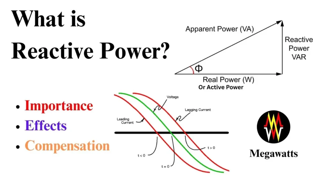
Reactive power, in an AC circuit, is the rate of energy that flows in and out of inductive and capacitive elements. As these elements result in a phase difference between voltage and current, causing the energy to be alternately stored and released in the respective electric and magnetic fields, in every cycle. Thus, in every cycle, the reactive power flows between source and load, back and forth.
Table of Contents
Difference between reactive power and active power
While the active part of the power, or active power, is utilized in doing real work, the reactive power does no real work but is utilized for maintaining the electric and magnetic fields in the AC circuit. Active power is consumed by resistive loads, while the reactive power is utilized in capacitive and inductive loads. An increase in the active power improves the power factor, while the opposite is true for reactive power, as an increase in reactive power decreases the power factor. It may also be noted that the reactive component of power exists only in AC circuits.
| Parameters | Active | Reactive | Apparent |
| Unit | Watt | VAR | VA |
| Function | Useful work | Maintains electric and magnetic fields | Combined |
| Load | Resistive | Inductive and capacitive | All AC loads |
| Phase relation | In phase | Out of phase | Combined |
Role of inductive and capacitive elements in Reactive Power
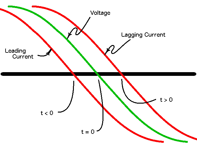
When AC voltage is applied across an inductive element, current flows in the inductive element, creating a magnetic field. This field also creates a back emf which opposes the change in current in the inductive element, causing the current to lag behind the voltage. Energy is used and stored in the creation of this magnetic field in the first half of each cycle, while the stored energy is returned to the source as the field collapses and reverses in the next half cycle.
This storing of energy in the magnetic field and releasing it as the field collapses creates the reactive power that oscillates between the AC source and the inductive load.

When the AC voltage is applied across a capacitive element, it reacts to the changing voltage by moving the charge. This creates a phase shift in which the current leads the voltage. The capacitive element stores the energy in the electric field and releases it during the first half and second half of the cycle, respectively, with alternating voltage.
This storing of energy in the electric field and releasing it back as the field collapses in the second half of the cycle creates the reactive power that oscillates between the source and the capacitive load.
Why is Reactive Power Important?
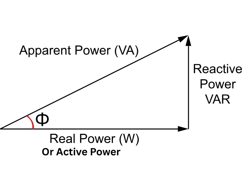
Power factor is the ratio of active power to apparent power. From the power triangle, the apparent power comprises both reactive and active power components.

P = Active power
Q = Reactive power
S = Apparent power = √(P2+Q2)
And Power factor, PF = P/S
The power factor ranges from 0 to 1. A unity power factor means no reactive component is present in the AC circuit. A lower value of power factor indicates more reactive component is present in the circuit as the apparent power, S, increases while the active power, P, remains the same.
A low power factor in a circuit results in an increase in current for the same value of active power. This causes the power loss I2R to increase. More reactive power in a circuit thus results in lower electrical efficiency, and increased voltage drop in a transmission line because of transmission line resistance.
Effects on generation and transmission capacity requirements
Generators are rated in terms of apparent power, MVA, and generate both reactive and active power. When the reactive part increases, active power generation reduces to match the MVA rating. Also, an increase in the reactive part of power increases the current in the generator’s winding, which results in the heating of the winding. Excessive reactive power demand has to be matched by the generator by increasing excitation, which results in the overstressing of the rotor winding insulation.
Reactive power in the transmission line decreases the active power delivery capacity of the line. Since with an increase in reactive part of power, apparent power also increases, which draws more current per MW delivered. This drawal of more current can hit the thermal capacity of the transmission line, and it may result in overheating of conductors. Also, the line losses will shoot up with the increase in the reactive component of power. When the reactive power demand is high in a long transmission line, the remote end voltage will drop, with very low voltage, active power delivery will be inefficient, and often result in the collapse of voltage.
How is Reactive Power Measured and Calculated?
Reactive power is denoted by Q and its unit is VAR, that is volt-ampere-reactive. It is expressed as Q = VI sin (Φ), where V is the rms voltage, I is the current and Φ is the phase angle. In case of a three phase system Q = √3 VI sin (Φ), where V is the line voltage and I is the current and Φ is the phase angle.
Reactive power can also be expressed as Q = P tan(cos-1(power factor))
From power triangle, Q = √(S2-P2).
The Reactive component of power is basically measured by the energy meters connected in the Substation which digitally computes the VI sin (Φ), by combining the voltage and current signals from the field.
Reactive Power Compensation Techniques
Capacitor banks are basically a group of capacitive elements connected together in series or parallel, which can counter the reactive part of power that is demanded by the inductive load, such as nearby industries, motors, transformers, and transmission lines. The capacitor bank fixes the lagging phase shift caused by the inductive load by generating a leading phase shift, where the current leads the voltage. Capacitor banks also improve the power factor, improve voltage for nearby loads, and can improve the transmission line voltage.
A synchronous condenser is a synchronous motor with no load attached to the shaft, which is connected to the grid and is capable of smoothly supplying and absorbing the reactive component of power. It has a DC field winding and an auto voltage regulator, which changes the field current. For under-excitation, it can consume the reactive component of power and act like an inductive element, or supply the reactive component of power and act like a capacitor when over-excited.
The static var compensators are an electronic system to control the reactive power in an AC system. It has shunt capacitors and a shunt reactor for supplying and absorbing the reactive power. Further, the supply and absorption are controlled by the control unit, which provides stability to the grid upon voltage fluctuation. When the voltage is low, reactive power is supplied by the shunt capacitor, increasing the voltage, and absorbed by the shunt reactor when the voltage rises, thus maintaining the voltage level.
A STATCOM is a static synchronous compensator that is based on advanced power electronics, It provides dynamic voltage and reactive power support. It acts as a voltage source inverter that can generate voltage at various magnitudes and phases. It has a control system that, on the basis of voltage, commands the system to absorb or supply reactive power. It is used in renewable energy farms to manage the voltage fluctuation, transmission substations for providing quick action voltage stability.
| Equipment | Type | Speed of response | Application |
| Capacitor bank | Passive | Slow | Power factor correction at distribution level |
| Synchronous condenser | Rotating | Medium | Voltage stability at transmission level |
| Static VAR compensator | Power Electronics | Fast | Voltage control at transmission level |
| STATCOM | Power Electronics | Very Fast | Voltage regulation at grids |
Conclusion
It should be clear that travel of the reactive component of power over distance causes voltage drop, hence injection of reactive power locally in the distribution level boosts the voltage and adds in less voltage drop on the transmission system as reactive power is not drawn from the transmission system. However, if it is drawn from the transmission system, then a voltage drop will occur because of the transmission line impedance, and transmission efficiency will suffer.
This article is a part of the Energy storage and reactive power compensation page, where other articles related to the topic are discussed in details.
