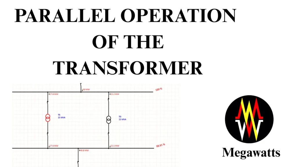
Parallel operation of the transformer is a method of operating two or more transformers that are primarily connected to a common source and whose secondary sides cater to a common load such that the load is shared between the connected transformers.
Table of Contents
Parallel operation of the transformers is considered when the utility’s load demand is increased and it becomes impossible to supply the increased load with the present rated transformer available. Hence, a similar-rated transformer is added adjacent to the existing transformer, parallelly operated which increases the supply capacity of the substation.
The arrangement of parallel operation of the transformers behaves like a single transformer unit, seamlessly sharing the load. However, there are certain fixed conditions to be met for the successful parallel operation of the transformers as well as certain conditions for the best optimal results.
CONDITIONS FOR PARALLEL OPERATION OF THE TRANSFORMER
Same vector group:
The vector group of all the transformers to be connected in parallel has to be the same in order to nullify the difference in winding configuration and any phase angle shift between the transformers.
If the winding configuration is different, voltages at the secondary will be different. Ynd and Ynyn transformers cannot run parallel because one will have a line voltage at the secondary, and the other will have a phase voltage.
If the phase angle shift between the primary and secondary of different transformers is different, then there will be a voltage differential in the secondaries of the connected transformers. The magnitude of voltage can be the same but the vector (phase angle) will be different.
This difference will cause a resultant voltage to drive current into the low-impedance transformer winding causing thermal instability. In severe cases can damage the insulation of the transformer’s winding.
Same polarity:
Parallel operation of the transformers must be checked for the same polarity. Polarity is the instantaneous direction of voltage in the secondary of the transformer with respect to the primary. If the direction of input voltage is in the same direction as the secondary induced emf, it is called subtractive polarity, while if the directions are opposite, it is called additive polarity.
If all the parallelly connected transformers do not have the same polarity, then it will result in a dead short circuit in the secondary bus.
Same phase sequence:
The phase sequence is the sequence in which the voltage or current reaches the peak value. The primary winding of a limb induces an EMF into the secondary based on a time-phase relationship. The peak value of parallelly connected transformers can be altered and matched by altering the turns ratio, but the phase sequence can never be different.
For parallel operation of the transformers, if the phase sequence is not correct, then it will result in short circuit of phases in every cycle.
Same frequency rating
For parallel operation of the transformers, all the transformers have to operate at exactly the same frequency, if suppose transformer A is operating at 50 Hz and B at 48 Hz, it will result in a phase drift relative to time, making the waveforms unsynchronized. The secondary voltages of the transformers will fluctuate and a circulating current will be established between the transformers.
CONDITIONS FOR OPTIMUM PARALLEL OPERATION OF THE TRANSFORMER
Same voltage ratio:
The transformers parallelly connected, can conveniently have identical voltage ratio, because if the voltage ratio of the connected transformers are different, the same primary voltage from the source will transform into different secondary voltages in the secondary bus and as the secondary windings are shorted by the bus. It will result in a circulating current between the transformers. As the impedance is very low, the magnitude of this circulating current will be very high. It can potentially damage the insulation, lower the efficiency as losses will be more, and lower the service life of the lower secondary voltage transformer.
Unequal voltage ratio transformers can be operated parallelly but without the best results. However, a tolerance of 0.5% is acceptable.
Same percentage impedance
Transformers percentage impedance is a very important factor for parallel operations. We can use different percentage impedance transformers to operate parallelly but practically it defeats the purpose of parallel operation if we are considering parallel operation to increase the power supply capacity of the substation.
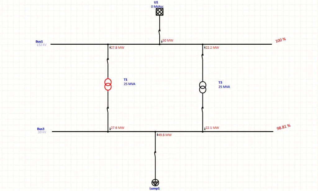
Consider a Substation with two power transformers A and B parallelly connected, 25 MVA each with a percentage impedance of 10% and 12.5% respectively. Considering the unity power factor the load sharing for 25+25 = 50 MVA full load capacity will be,
Transformer A, Load share = (Zb/Za+Zb) 50 = (12.5/10+12.5) 50 = 27.78 MW
Transformer B, Load share = (Za/Za+Zb) 50 = (10/10+12.5) 50 = 22.22 MW

Now say transformer A’s load limit is set at 25.5 MW by the protective relays. Therefore it can be inferred from the above that before reaching the full load capacity, transformer A will trip because of the overload and as transformer A trips, transformer B will also trip as it will fail to supply the entire load alone, overload trip. The total loading capacity because of different impedances will be practically reduced to 46 MW approximately for parallel operation. Therefore, it is best to have the same percentage impedance for the parallel operation of the transformer.
Same Tap changers
For parallel operation of the transformers, it is recommended to have the same tap changers with identical OLTCs so that all the transformer’s tap changes can be coordinated and synchronized as in the case of a master-slave mechanism. Otherwise, the voltage difference will be caused in the secondary common bus, resulting in a circulating current, that will limit the efficiency, increase losses, and decrease the service life of the transformers.
ADVANTAGES OF PARALLEL OPERATIONS
Redundancy: Parallel operation of the transformers is basically adopted in the utility practice because the inclusion of two or more transformers with the same rating enhances redundancy than installing a single transformer with an equivalent rating. This reduces the chances of a total blackout.
Operational reliability and flexibility: In case of a breakdown, a single-unit transformer will lead to an entire load disconnection. But in the case of parallel operation of the transformer, where there are at least two transformers connected, the breakdown of one unit will lead to partial load disconnection. This increases the operational reliability and flexibility.
Efficiency: Also during low load demands, parallel operation of the transformer aids in to use of a single transformer unit at near full load, while the other can remain out of service, this increases the efficiency of transformation.
Availability during maintenance: Preventive and necessary maintenance works can be done without the complete shutdown of the substation. This improves the power availability of the system.
DISADVANTAGES OF PARALLEL OPERATIONS
Higher short circuit current: In parallel operations of the transformer, the overall source impedance decreases and this results in a higher short circuit current in the secondary during a fault. Hence, using a current-limiting reactor can be an effective solution.
Uprating of secondary side circuit breakers: As the short circuit current increases because of low impedance, the secondary side circuit breaker therefore needs upgrading and match the higher breaking current capacity.
Bus re-configuration: During a short circuit fault in parallel operation of the transformers, the bus has to handle increased short circuit current levels before the isolation of the fault. Hence, it should be configured to withstand the high short-circuit current (upsizing the conductors or using bundled conductors per phase) and mechanical stress (increasing disc insulators or upsizing) during the nearby fault. It may be noted that electrical clearances must be checked in the upgraded design.
Complex protection: The protection becomes more complex with an increasing number of transformers in parallel as the secondary fault current rises, the fault path increases, and uneven current sharing leads to difficult threshold settings.
This article is a part of the Transformer page, where other articles related to the topic are discussed in details.

