Frequency meters are instruments that are widely used for the measurement of the frequency in various power system applications. Frequency is a very critical parameter in the electrical system as system stability, equipment performance, grid reliability, power quality, and economic efficiency all depend heavily on system frequency. Hence the frequency meters are of great importance.
Table of Contents
Types of Frequency meters
There are four major types of frequency meters used and are discussed below
- Electrodynamic-type frequency meters
- Tuned reed Frequency meters
- Saturable core frequency meters
- Digital frequency meters
Electrodynamic-type frequency meters
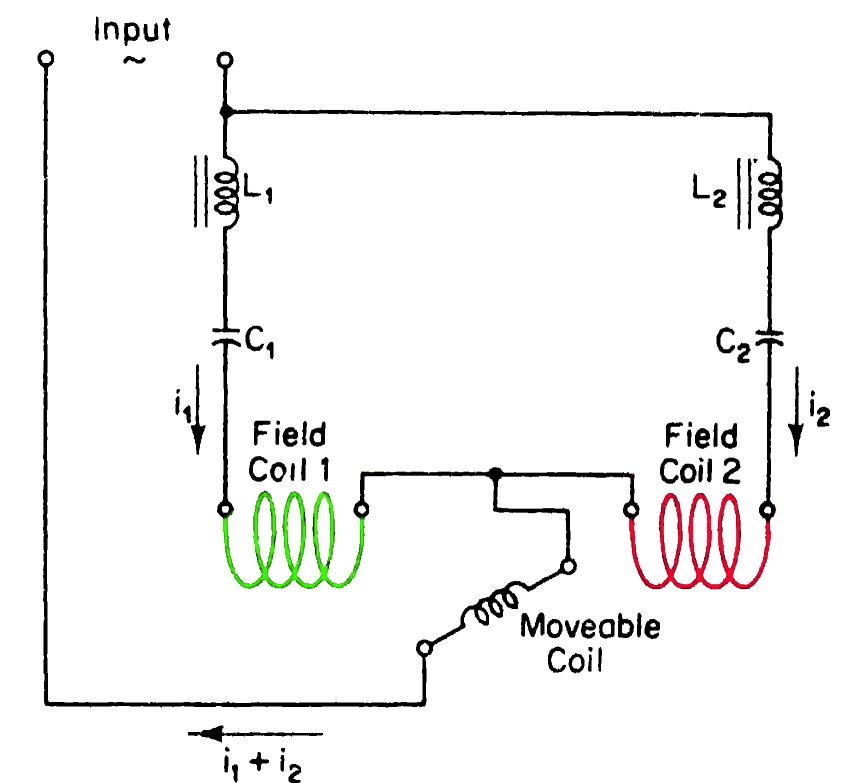
The use of tuned circuits is found in these types of instruments. In this type of frequency meter, the field coil forms part of two resonant circuits which are separate. As shown in the diagram, the field coil 1 which is in series with inductor L1 and capacitor C1 forms a resonant circuit that is tuned to a frequency below the low end of the scale of the instrument.
Similarly, the field coil 2 in series with inductor l2 and capacitor C2 forms a resonant circuit tuned to a frequency higher than the high end of the scale of the instrument. When the power frequency is applied, the circuits would be tuned to a frequency say 40 Hz and 60 Hz, with 50 Hz in the middle of the scale. The field coils are arranged as shown in the diagram and return the current i1 and i2 through the winding of the movable coil. Thus a torque is applied on the movable element which is proportional to the currents flowing through the moving coil.

The current through the moving coil is the sum of currents flowing through the field coils. For any applied frequency within the range of the instrument, the circuit of the field coil 1, operates above the resonant frequency with current i1 lagging the applied voltage. The circuit of the field coil 2 operates below its resonant frequency, which is capacitive with current i2 leading the voltage. The torque produced by these two currents on the moving coil is in opposition while the resulting torque is the function of the frequency of the applied voltage.
Any frequency within the range of the instrument causes a resulting torque on the moving element which results in the deflection of pointers in the graduated scale calibrated according to the range of operation. A restoring torque is provided by the vane mounted on the moving coil. The function of this restoring torque is to bring back or return the pointer back to its original position once the power frequency voltage is withdrawn. This torque also stabilizes the deflection of the pointer so that an accurate representation of the frequency of the input signal is possible.
Characteristics
- It is a very precise instrument
- The construction of these instruments is robust
- These devices are sensitive to external influence and may impact accuracy
- Maintenance is required to ensure precise measurement.
Tuned reed Frequency meters:
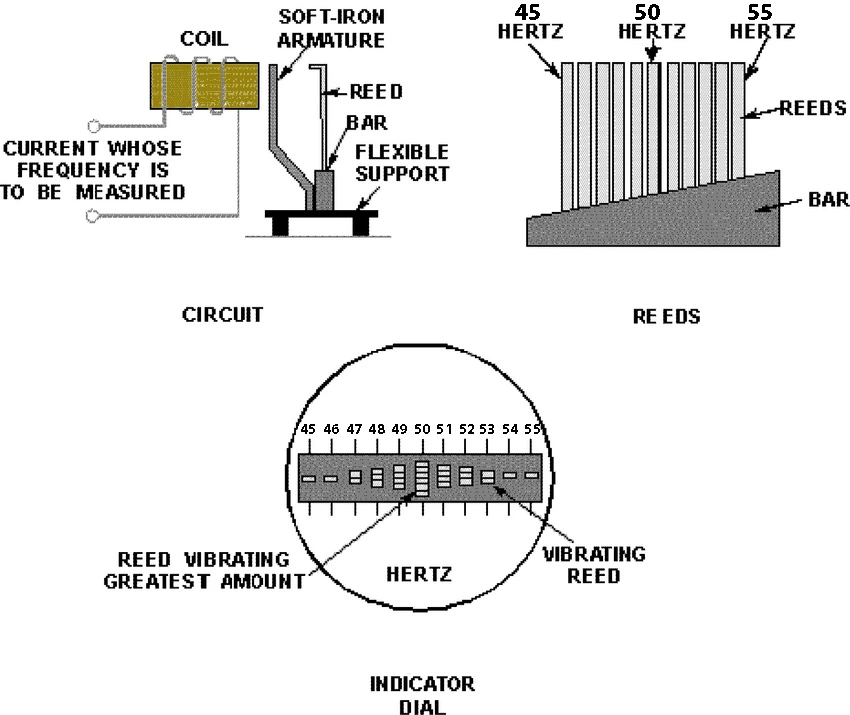
This type of frequency meter works on the basis of the mechanical resonance principle. A series of reeds are fastened to a flexible base which is common, mounted on an armature of an electromagnet. The coil of the electromagnet is energized with the AC supply whose frequency is to be measured. The reeds are tuned into exact natural frequency by careful selection of their length and mass. As the coil is energized, the reed with the closest natural frequency to the frequency of the system builds up vibration.
This vibration is visible through the front of the meter where the vibrating tip of the reed is visible through a window. If the frequency of the system is intermediate between two natural frequencies of the reeds, both reeds will vibrate and the line frequency will be the closest to the reed with the largest vibration. Interpolation of the line frequency can thus be easily made as the natural frequency of the reeds is exact. These meters are simple in construction and rugged.

Characteristics
- The design allows selective tuning for specific frequencies
- It is compact in size
- These instruments are less expensive.
- These instruments are subjected to mechanical wear over time
- Damping reduces the responsiveness of these meters
Saturable core frequency meters:
These types of frequency meters can handle a wide range of frequencies comfortably. A saturable core frequency meter consists of a transformer with two cores and a yoke. One of the cores is nonmagnetic while the other is magnetic. The magnetic core saturates at very low values of emf and current. The yoke is also magnetic but because of its large cross-section, it does not reach saturation.
The primary winding of the transformer is wound around both the cores while the secondary winding consists of two parts. One half is wound around the magnetic core and the other half is on the non-magnetic core. The secondary windings are connected in series such that the voltage induced in the windings opposes each other. When power is supplied to the primary winding, a very small voltage is induced in the secondary winding because of the low saturation value of the magnetic core.

As the core saturates, the rate of increase of induced voltage in the winding will be that of the non-magnetic core. Therefore, canceling out the rate of increase of induced voltage as the emf in the secondary winding opposes each other. The secondary voltage is thus not a function of the primary voltage but a function of the system frequency. Thus, the secondary output is then rectified and applied to a DC meter whose deflection is proportional to the frequency of the system and the meter is calibrated in terms of frequency.
Characteristics
- These types of instruments are highly sensitive and are capable of detecting small changes in frequency.
- They can measure a wide range of frequency variations.
- These instruments offer a good linear response of frequency.
- These designs are expensive.
Digital frequency meters
In digital frequency meters, the input signal is converted to a trigger pulse and applied to an AND gate, the signal’s frequency is converted then to a train of pulse for each cycle. An electronic counter then counts the number of pulses occurring in a definite time interval. Since each pulse represents a cycle of the signal, the number of pulses is a direct indication of the frequency of the input signal.

The signal is often amplified before applying to the Schmitt trigger. The Schmitt trigger converts the amplified input signal to square waves. The output of the Schmitt trigger is a train of pulses, one pulse equating to one cycle of the signal. These output pulses are fed to the START/STOP gate. When this gate is ON the input signal passes directly to the electronic counter, which counts the number of pulses. The counter then displays the number of pulses that have passed in the time interval between start and stop.
Characteristics
- It gives precise measurements with high-resolution
- These instruments reduce the parallax error.
- These can measure a wide range of frequencies
- Many digital frequency meters have the feature of data logging
- Digital meters are more expensive than analog meters
- Their display requires a separate power source.
This article is a part of the Metering page, where other articles related to the topic are discussed in details.


https://cr-v.su/forums/index.php?autocom=gallery&req=si&img=4015
Awesome https://is.gd/tpjNyL
Awesome https://is.gd/tpjNyL