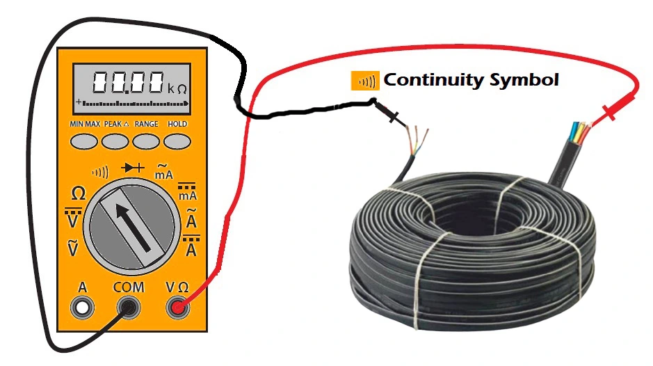
Electrical continuity essentially means that there exists a conductive part, through which electricity can flow sufficiently. Electrical continuity can present itself in the insulated electrical part making it unsafe for further operation or is a much-needed aspect for the conductors for efficient propagation of electricity into any circuit.
Table of Contents
Importance of electrical continuity
Electrical continuity is a very important factor in the operation of electrical circuits. It ensures proper functioning of the circuit indicating current can flow through the circuit. if there is any break in the continuity, the circuit won’t function as it should.
Electrical continuity ensures proper connection of the circuit elements thus avoiding overheating due to loose connection and short circuit chances. It also maintains safe voltage and current levels in the circuit in case of overload and other fluctuations.
In communication circuits, it ensures proper data transfer maintaining the signal quality. Interruption in the circuit leads to data loss.
Inspection for electrical continuity is a very common diagnostic step that helps in identifying the fault and thus making repairs faster.
Testing of electrical continuity
For conducting the electrical continuity test we need tools like a Digital multimeter or continuity tester.

Following are the steps for conducting the test
- Connect the probe of the multimeter to the COM port and another to the VΩ port.
- Configure the multimeter to continuity test mode by turning the knob.
- Test the multimeter by joining the two remaining ends of the probes, if the meter emits a beep sound and shows a reading close to 0 Ω, the meter is ready to conduct the test.
- Now connect the two ends of the probes to the two leads of the test subject be it an electrical wire or any component in the circuit.
- Wait for the continuous beep sound from the multimeter.
- Inference: If the multimeter emits the beep sound with a minimum reading in Ω, the test component has electrical continuity. If no sound comes from the multimeter, the test component has a broken electrical connection or an open circuit issue, often displayed as OL or infinite resistance, which will require an immediate fix.
- After the test is completed we must ensure that the multimeter is turned off.
Precautions before the continuity test
Following are the necessary precautions to be taken before testing for continuity
- Firstly ensure that the circuit component under test has to be put out of service or disconnected from the power source.
- The rating of the testing tool has to match the voltage rating of the circuit.
- The connecting leads of the multimeter should not be leaking current or it should not be damaged.
- The testing area should not be wet.
- Capacitors in the circuit under test can hold a charge even after disconnection from the power source. So we must ensure that the circuit is fully discharged before the test.
Applications of electrical continuity
- Electrical continuity tests help determine the functionality of a circuit and provide information if some circuit element is disconnected or identify faulty connection.
- During wiring inspection, it ensures secure connections promoting safety and proper functioning of the wiring once the power source is turned ON.
- While the continuity test is being performed the multimeter also shows the resistance of the circuit under test and hence it helps in identifying the resistance measure of the circuit or component.
- The continuity test is very important for ensuring the proper connection of grounding and ensuring electrical safety.
- It aids in the quick identification and repair of certain faults in low-voltage electrical circuits.
- In signal circuits, the continuity test promotes fewer data losses by ensuring proper connections of the sensitive circuitry.
- We can identify if an insulated cable, electrical fuses etc are conductive and usable or not by the help of continuity test.
Factors Affecting Electrical Continuity
Electrical conductivity and continuity are almost similar and hence the affecting factors are discussed below:
- Loose electrical connections lead to high resistance and interrupt the electrical continuity.
- Corrosion of the electrical terminals due to oxidation impacts the flow of electricity.
- Insulation damage can lead to short circuits and open circuits affecting the current flow.
- Extreme temperature can lead to an increase in resistance thus affecting the continuity.
- Longer wires in low-voltage circuits increase the resistance affecting continuity.
- Moisture dust and debris ingress can promote corrosion affecting the continuity.
- Increased mechanical stress over time can hamper the continuity.
FAQ’s
What is the meaning of electrical continuity?
The practical meaning is the presence of electrical conductivity in a test object through which electrons can easily flow with minimum to no restrictions.
What is a good continuity reading?
For domestic wiring purposes, any resistance below 2 ohm is considered excellent continuity. For other purposes, it depends on the application and type and should match the manufacturer’s rating.
What is continuity vs resistance?
Continuity widely gives the idea of the presence of conductivity in the circuit. if the circuit is open or not. However, the resistance gives the measure of opposition to the current flow in a circuit. A low resistance value in a circuit indicates good conductivity, very high resistance value indicates the absence of conductivity.
What is continuity range?
Most multimeters indicate continuity in the range of 0-50 ohms by emitting a continuous beep sound as long as the probe touches the test object.
This article is a part of the Testing and commissioning page, where other articles related to topic are discussed in details.

