Principle to Determine Maximum Grounding Grid Current
The maximum grounding grid current to earth refers to the maximum fault current which flows into the earth through the grounding grid under the fault conditions within the substation, or which flows into the grounding grid from the earth when the fault occurs outside the substation, it is an important parameter that must be fully examined in the grounding grid design.
Table of Contents
Most of the time, in the substation’s grounding design, the maximum grounding grid current, IG generates the most serious touch potential and step potential, which happens to be the most dangerous situation.
When ground faults occur, the earth is used as the return path of the fault current to the neutral of the system. Only a part of the total fault current flows from the grounding grid into the earth. The fault which appears in the substation may not generate the most serious case with the largest part of the fault current flowing into the earth from the grounding grid, because a transformer with the neutral grounded has a direct path for the fault current which returns to the neutral of the system, rather than into the earth when the substation has a circuit reference ground.
The fault which generates the maximum grounding grid current may be a transmission line ground fault at a certain distance from the substation. But, fact is that there is no simple rule which can be used to determine which fault and location will lead to the maximum grounding grid current flowing into the earth from the grounding grid, or flowing into the grounding grid from the earth.
Types of Substation Ground Faults Which Can Generate Maximum Grounding Grid Current
Basically, the ground faults of a substation and power plant can be divided into four types.
Type 1
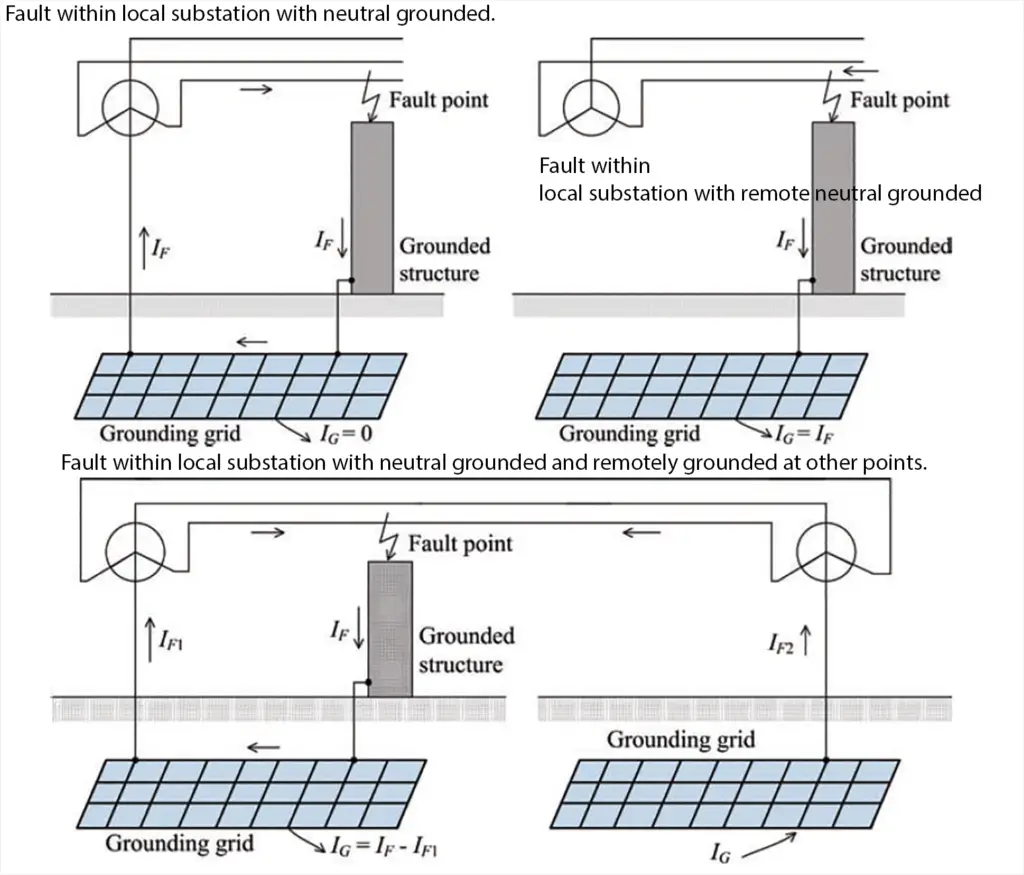
Fault is within local substation only the neutral of the substation is grounded and the fault current flows from the fault point through the metal path that is composed of the grounding grid. There is no current flowing into the earth.
Type 2
Fault within local substation where the neutral is only grounded remotely and all the fault current passes from the fault point through the substation grounding grid into the earth.
Type 3
Fault is within local substation, when the power system is grounded both inside and outside the substation which forms a multi-point grounded system, the fault current through the substation grounding grid returns to the neutral of the substation, as well as through the earth returns to the remote neutral. This is the part of the fault current which generates a ground potential rise that is dangerous.
Type 4
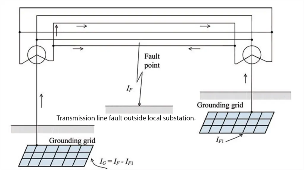
Fault in the transmission line outside of the substation, when the power system is grounded inside and outside the substation to form a multi-point grounded system, the fault current returning to the substation grounding grid from the earth which depends on the shunt of the remote grounding device.
Location of the Maximum Grounding grid Current
For a power system, the most serious fault generally refers to the case with the maximum grounding grid current IG. Because the current is proportional to the zero-sequence or grounding fault current, or the fault current division factor, and because the current division has almost nothing to do with the fault type, the most serious fault type can be defined as the fault which results in the largest zero sequence current I0 or ground fault current (3I0) flowing into the earth from the grounding grid.
For a given location, if the positive, negative and zero sequence impedance of the fault point Z1, Z2 and Z0 meet Z1Z0 > Z22 , then the single line to ground fault is the most serious fault type.
If they meet Z1Z0 < Z22 , then the line to line to ground fault is the most serious fault type.
Under normal conditions the assumption is that Z1 = Z2, the conditions under which the former single line to ground and line to line to ground are the most serious fault types change to Z1<Z0 and Z1>Z0 respectively.
To determine the maximum grounding grid current IG, a number of issues should be considered as follows.
The location where the most serious fault occurs may appear either in the high-voltage side, or in the low-voltage side. But in both cases, it may occur either within the local substation or on a transmission line outside the local substation. When the fault relates to a metal structure which has an electrical connection with the grounding grid, the connection resistance then is ignored, and then the fault can be classified as a fault within the local substation. There are no fixed principles to determine the location of the most serious fault.
The following discussion can provide a reference, but it should be noted that these discussions do not represent all the location scenarios of the faults producing the maximum grounding grid current.
1. For a distribution substation whose transformers are grounded on the distribution side, IG , maximum grounding grid current generally appears in high-voltage side of the transformer. However, if the ground fault current source of the high-voltage side is weak, or when parallel operation of transformers leads the ground fault current source of the low-voltage side to be high, the maximum grounding grid current appears as a certain ground fault somewhere on the distribution circuit.
2. For a ground fault appearing on the low-voltage side of the secondary side of the transformer with neutral grounded, the transformer will only allow the fault current to flow through the conductors of the grounding grid, without leakage current flowing into the soil. Therefore, the fault current has no contribution to the ground potential rise.
3. If the ground fault takes place at a remote location of a distribution feeder outside the local substation, the majority of the fault current will return to the fault source through the substation grounding grid and the neutral of transformer, thus there will be a substation ground potential rise.
4. In a transmission substation with three-winding transformer or automatic adjusted transformer, the case becomes more complicated. Maximum Grounding Grid Current, IG may be caused by the transformer’s fault in either the high- or low-voltage side, and hence the two cases should be checked. For each case, it can be assumed that the fault is in the terminal of the transformer within the substation.
In contrast, if the transformer has a dominant contribution to the grounding grid current, then the location of the most serious fault may be on the transmission line outside the substation. From the above analysis we know that, for a particular system, we should take into account several fault locations leading to the maximum grounding grid current. For each possible location, we should calculate its corresponding value of the zero-sequence current.
For special circumstances, the cases may be more complex. The fault duration depends on the type of the protection procedures used, the fault location and the clearing time of the primary or backup protection.
This not only affects the decrement factor Df, but also affects the human body’s permitted voltage.
If a particular fault has a relatively long clearing time, the corresponding tolerant voltage will reduce. Even if the grounding grid current is not the largest, the situation can still lead the fault to be a very serious one. This situation generally appears in the Delta-Star grounded transformer which is fed from the relatively weak side of the fault source, and the fault appears at a certain distance from the rural distribution feeders. In this case the fault current on the high-voltage side (D side) may be relatively lower, while the fault on the low-voltage side (Y side) mainly depends on the faults of the transformer and feeder.
If we consider the backup protection time, for example a fault appears on a feeder within a few kilometers of the substation, the backup protection of the fault for the circuit breaker needs a few seconds to remove the fault. Under these circumstances, the permitted voltage will evidently be lower than the corresponding permitted voltage when the ground fault is on the high-voltage side of the transformer.
So the most serious fault type and location must take into account not only IG, but also the permitted voltage based on the fault clearing time.
Maximum Grounding Grid Current
The fault current division factor is a factor representing the inverse of a ratio of the symmetrical fault current to that portion of the current that flows between the grounding grid and the surrounding earth.
The design value of the maximum grounding grid current is defined as:
IG = Df Ig , where Df is the corresponding decrement factor of the fault duration tf; Ig is the rms symmetrical grid current in A.
The rms symmetrical grid current is the portion of the symmetrical grounding fault current which flows into earth from the grounding grid, which can be denoted as:
Ig = Sf If , where If is the rms symmetrical grounding fault current in A and Sf is the fault current division factor, which is the ratio between the fault current amplitude and the portion of fault current which flows from the grounding grid to the surrounding earth.
In fact, during the fault process, the fault current division factor varies, and this is related to the attenuation velocity of the change in fault source and the fault clearing time of the protection device.
However, for the purpose of calculating the design value of the maximum grounding grid current, it is assumed that the fault current division factor Sf remains unchanged through the whole fault duration.
The rms symmetrical grounding fault current If can be obtained by:
If = 3I0 , where I0 is the zero-sequence fault current in A.