GROUNDING RESISTANCE
Grounding resistance is the ratio between the difference of potential of the grounding device to the earth and the current flowing to the earth through the grounding device. It is related to the soil characteristics and the size and shape of the used grounding device.
Table of Contents
COMPONENTS
The resistance in soil encountered when a current flows into the soil is called the current-dispersing resistance. The grounding resistance consists of the ground lead resistance, the contact resistance between the ground lead and the grounding device, the resistance of grounding conductors, the contact resistance between the grounding electrode and soil, and the current-dispersing resistance of the soil.
Ground Lead Resistance
It refers to the electrical resistance of the material used as grounding lead for the equipment to be grounded in the grounding system. If the lead resistance is high, it can impede the flowing current resulting in higher levels of touch voltage and increasing risk to safety.
Contact resistance between the ground lead and the grounding device
It is another critical factor in ensuring an effective grounding system. It refers to the resistance encountered at the point where the ground lead connects to the grounding electrode such as a ground rod, plate, or conductor. Low resistance in the contacts ensures easy flow of fault currents from the equipment or the system, through the ground lead and into the grounding electrodes.
The resistance of grounding conductors
The resistance of the grounding conductors, which forms the connection from the lead to the electrode also contributes to the grounding resistance. The choice of material for the conductor thus plays an important role in the effective grounding. Power transformers use copper as the grounding conductor for grounding of neutral while the body earthing is done with GI flats.
The contact resistance between the grounding electrode and the soil
It is the resistance at the contact between the earth and the grounding electrode. It is normally seen in practice that the deeper the electrode is buried, the lower this contact resistance. However, the type of soil, design, and sizing of electrodes also play a role in the effective contact resistance. Depending on the soil structure the contact resistance between soil and electrode can act much like a point resistance than surface contact resistance.
The current-dispersing resistance of soil
Because the current-dispersing resistance is much greater than the other four kinds of resistance, the grounding resistance of a grounding device approximates the current-dispersing resistance.
Usually, the grounding resistance of a grounding device is calculated by numerical methods or empirical formulas, and it is the current-dispersing resistance of the soil, but the actual measured value is generally greater than the calculated result. This is because the actual contact between the grounding electrode and the soil is not a complete surface-like contact, but a point-like contact.
This leads to a high contact resistance between the grounding conductors and the soil, especially in rocky areas. This contact resistance has an uncertain value, which is related to the soil compression degree during construction, the soil particle status, the soil moisture, and so on, but the contact resistance, in the calculation formula is not reflected.

For example, as shown in the Figure above, the radius of a hemispherical grounding device is r0, and the current flowing into the earth through the grounding device is I, assuming the terra firma is a homogenous soil with a resistivity of 𝜌. The potential of the point with a distance r from the center of the hemispherical grounding device can be calculated by the potential formula of a point current source, which is:
V = I 𝜌 / 2 π r
The potential v0 of the grounding device can be calculated by the above equation when r = r0
V0 = I 𝜌 / 2 π r0
The potential distribution of the hemispherical grounding device is shown.
According to the definition, the grounding resistance of a hemispherical grounding device is:
R = V0 / I = 𝜌 / 2 π r0
Relationship between Grounding Resistance and Capacitance
According to the similarity between the electrostatic field and the current field that is constant, it is easy to obtain the relationship between the grounding resistance and the capacitance of a grounding device:
R = 𝜌 ϵ / C
where ϵ is the dielectric coefficient of the soil (with units of F/m) and C is the capacitance of the grounding device with respect to infinity (with units of F).
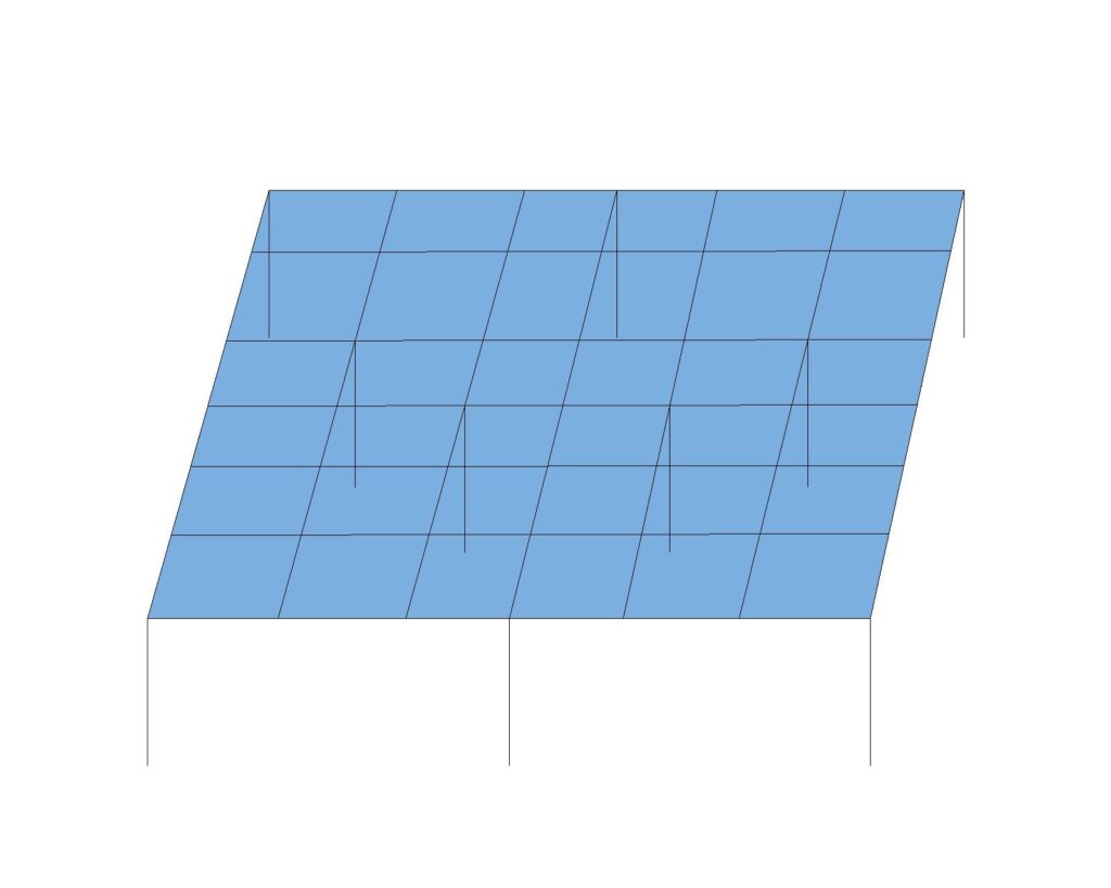
When the resistivity 𝜌 and the dielectric coefficient ϵ of soil are constants, the capacitance becomes inversely proportional to its size. From the above equation, we can ascertain that the grounding resistance of the grounding device is inversely proportional to its capacitance. Thus, the larger the size of the grounding device, the greater the capacitance and the lower the grounding resistance. For actual grounding projects, the grounding resistance of an earth grid is basically determined once the area of the grid is defined.

A grounding grid that consists of many horizontal conductors can be approximated to an isolated plane, whose capacitance is mainly determined by its area. If short vertical ground rods are connected to this plane, they have little influence on the capacitance and so the grounding resistance decreases just slightly. As per the analysis, the grounding resistance is highly reduced only when the length of the vertical ground rods can match the equivalent radius of the earthing grid.

