Capacitance of Parallel-Plate Capacitor
The capacitance of a capacitor can be calculated from its electrical properties using the relation C = Q/V. However, at times it is desirable to calculate the capacitance of a capacitor in terms of the dimensions and relative permittivity of the dielectric or insulating medium. Although there are many forms of capacitors, the most important arrangement is the parallel plate capacitor.
Table of Contents
Capacitance of Parallel-Plate Capacitor with Uniform Medium
Let us take a parallel plate capacitor that has two plates, each with an area of A square metres which are separated from each other by a uniform dielectric medium of thickness d metres with relative permittivity of εr as shown below. Let a potential difference of V volts be applied between the plates and place a charge of +Q and − Q on the plates. With reasonable accuracy, it can be assumed that the electric field between the plates is uniform.
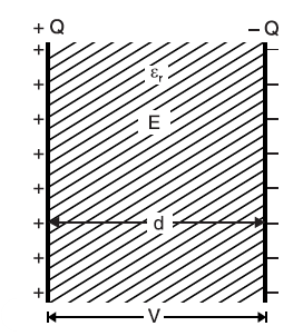
Electric flux density between plates is
D = Q/A coulomb/m2
The electric intensity between plates is
E = V/d
But D = ε0 εr E
or Q/A = ε0 εr V/d
or Q/V = (ε0 εr A) / d
The ratio of charge to voltage or Q/V is the capacitance C of the capacitor.
C = (ε0 εr A) / d …. For a medium
C = (ε0 A) / d …. For air
IMPORTANT POINTS:
Capacitance is directly proportional to relative permittivity εr and area of the plates A and inversely proportional to the dielectric thickness d.
The relative permittivity of the medium is the ratio between the capacitance of the medium to the capacitance of air.
Cmedium / Cair = εr.
Re-arranging the relation for C in air
ε0 = C d / A = farad * meter / meter2 = farad/meter.
Therefore, permittivity can also be measured in F/m.
Parallel Plate Capacitor with Composite Medium
In these parallel plate capacitors, let the space between the plates be occupied by three dielectrics of thicknesses d1, d2 and d3 metres and relative permittivities εr1, εr2 and εr3 respectively as shown in Figure. The electric flux density D in the dielectrics remains the same and is equal to Q/A, as the total charge on each plate is Q, hence Q coulombs is also the total electric flux through each dielectric.. However, the electric intensities of this parallel plate capacitor will be different in the three dielectrics and are given by;
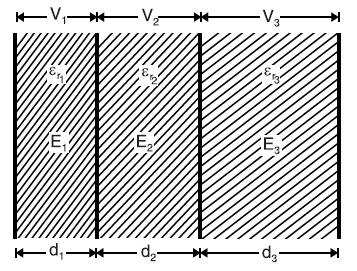
E1 = D / ε0 εr1 ; E2 = D / ε0 εr2 ; E3 = D / ε0 εr3
If V is the total potential difference across the capacitor and V1, V2 and V3 the potential difference across the three dielectrics of the parallel plate capacitor respectively, then,
V = V1 + V2 + V3
= E1d1 + E2d2 + E3d3
= (D / ε0 εr1) * d1 + (D / ε0 εr2) * d2 + (D / ε0 εr3) * d3
= D/ ε0 [ d1 / εr1 + d2 / εr2 + d3 / εr3]
= Q / (A ε0)[ d1 / εr1 + d2 / εr2 + d3 / εr3]; since D = Q/A
Or Q/V = A ε0 / [ d1 / εr1 + d2 / εr2 + d3 / εr3].
Since Q/V is the capacitance, therefore,
C = A ε0 / [ d1 / εr1 + d2 / εr2 + d3 / εr3] farad
Different cases
We shall discuss the following two cases :
Medium partly air in a parallel plate capacitor
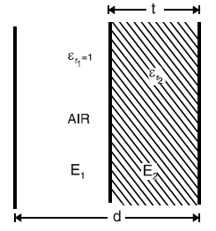
As shown in the figure a parallel plate capacitor has plates d metres apart. Suppose the medium between the plates consists partly of air and partly of dielectric of thickness t metres and relative permittivity εr2. Then the thickness of air is d − t. Using the relation above, we shall have
C = A ε0 / [(d-t)/1 + t/ εr2]; since relative permittivity of air is 1
= A ε0 / [d-(t-t/ εr2)] farad
When the dielectric slab was introduced in parallel plate capacitor
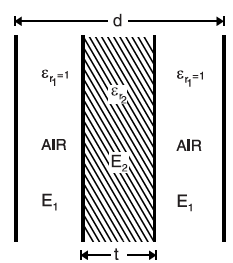
As shown in the figure a parallel-plate air capacitor has plates d metres apart. Suppose a dielectric slab of thickness t metres and relative permittivity εr2 is introduced between the plates of the capacitor. Using the relation above, we shall have
C = A ε0 / [(d-t)/1 + t/ εr2]; since relative permittivity of air is 1
= A ε0 / [d-(t-t/ εr2)] farad
Special Cases of Parallel Plate Capacitor
We have seen that the capacitance of a capacitor depends upon plate area, thickness of dielectric and value of relative permittivity of the dielectric. We consider two cases by way of illustration.
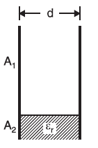
In the figure, it is shown that dielectric thickness is d but the plate area is divided into two parts; area A1 has air as the dielectric and area A2 has dielectric of relative permittivity εr. The arrangement is equivalent to two parallel capacitors. Their capacitances are :
C1 = A1 ε0 / d, C2 = A2 ε0 εr / d
Therefore, total capacitance for this parallel plate capacitor is:
C = C1 + C2
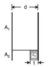
In the figure, it is shown that the plate area is divided into two parts, area A1 which has a dielectric (air) of thickness d and area A2 having a dielectric (εr) of thickness t and air occupies the remaining thickness.
This is equivalent to two capacitors connected in a parallel arrangement. Their capacitances are:
C1 = A1 ε0 / d , C2 = A2 ε0 / [d-(t-t/ εr)]
Hence, equivalent capacitance for this parallel plate capacitor is:
C = C1 + C2
Factors affecting the capacitance of parallel plates
The factors influencing the capacitance are listed below:
Area of the plates: It is evident from the formula that the capacitance is directly proportional to the area of the plates. The bigger the area the more will be capacitance as more charges will be attached to the enhanced surface area.
Size of dielectric: From the above formula for the capacitance, it is evident that the thickness of the dielectric d is inversely proportional to the capacitance. Hence, the increased size of the dielectric will decrease the capacitance.
Selection of dielectric material: The relative permittivity of the insulating medium ɛr is directly proportional to the capacitance. Hence, the capacitance is influenced by the selection of dielectric material.
Applications of Parallel plate capacitor
- Extensively used in RC timing circuits.
- Used in filtering circuits to filter out the noise.
- Used in amplifiers to block DC signals while coupling AC signals.
- Used in the flash for photography.

