Parallel Circuit
A parallel circuit is among the basic electrical circuits in which each end of the resistances are joined to form two common points so that there are as many paths for the electric current to flow through as the number of resistances connected.
Table of Contents
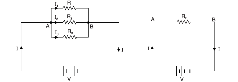
Consider resistances R1, R2, and R3 ohms connected in parallel across a battery of V volts as shown in Figure forming common points at A and B. The total current of the circuit I gets divided into three parts as I1 flows through resistance R1, similarly, I2 flows through R2, and I3 flows through R3. The voltage across each resistance is the same because the connection of the resistances via a common point to the voltage source is the same for the 3 resistances. Also, there are as many current paths as the number of resistances which is 3 in this case. According to Ohm’s law, current through each resistance is

I1 = V/R1
I2 = V/R2
I3 = V/R3
Now, I = I1 + I2 + I3
= V/R1 + V/R2 + V/R3
= V (1/R1 + 1/R2 + 1/R3)
Or, I/V = 1/R1 + 1/R2 + 1/R3.
Main Features of Parallel Circuits
The characteristics of a parallel circuit are cited below:
(a) The potential difference or voltage across each resistor connected in this system is the same.
(b) The current through any resistor is inversely proportional to its resistance.
(c) The total current in the equivalent circuit is equal to the sum of all the currents flowing through each of the resistors connected in parallel.
(d) The reciprocal of the total resistance is equal to the sum of the reciprocals of each individual resistance connected in the circuit.
(e) As the number of branches in the parallel circuit increases, the total resistance of the equivalent circuit decreases.
(f) The total resistance of the circuit is always less than the smallest of the resistances.
(g) If n number resistors, each of resistance value R ohms, are connected in parallel, then total resistance RT = R/n.
(h) The conductances are additive.
(i) The total power dissipated in the circuit is equal to the sum of powers dissipated in the individual resistances.
I/RP = 1/R1 + 1/R2 + 1/R3
V2/RP = V2/R1 + V2/R2 + V2/R3
PP = P1 + P2 + P3
A parallel circuit is also known as the current divider circuit. This consideration is due to the fact that the current through each resistor in the parallel branch is a fraction of the total circuit current. The fraction depends on the values of the resistors in the parallel branches.
Advantages of Parallel Circuits
The main advantage of a parallel circuit is the fact that the potential difference or the voltage across the terminal of each parallel branch resistor is basically the same or equal. This feature of the parallel circuit also adds to the following advantages:
(i) The equipment which are rated for the same voltage but with different power ratings can easily be connected in parallel and operated simultaneously. Thus a 230 V, 230 W television can operate independently in parallel with a 230 V, 10 W led lamp.
(ii) If there is a circuit break in any of the branches connected in a parallel arrangement, the other branches of the circuit will not be affected because of the above fault.
Due to these advantages, most of the electrical equipment are connected in parallel. Any equipment thus can be switched on or off without affecting other lights or equipment connected to the circuit.
Applications of Parallel Circuits
Parallel circuits find various applications in electrical and also in electronic circuits.
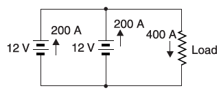
(i)Identical voltage sources that are connected in parallel provide much higher current capacity. The figure below shows two batteries used in cars of 12 V each, connected in parallel. Suppose the starter motor draws a 400 A at starting, then each battery will supply half of the current i.e. 200 A. A single battery is surely not enough to be able to provide a load current of 400 A. Also, the two batteries connected in parallel will supply a given load current twice the time compared to a single battery before full discharge is reached.

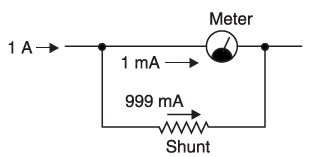
(ii) The figure below shows another application for parallel connection. A low resistance also called a shunt, is connected in parallel with an ammeter to increase the range of the measurement in the ammeter. If the shunt is not used, the ammeter is able to measure currents up to 1 mA. However, the use of a shunt permits to measurement of currents up to 1 A. Thus, the shunt increases the range of the ammeter.

Majorly used in domestic power connections where equipment connected requires the same voltage for multiple device connections

