Leakage Resistance of a Capacitor
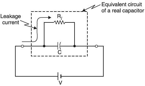
The resistance of the dielectric of the capacitor is called the leakage resistance of a capacitor. The dielectric medium in the ideal capacitor is considered a perfect insulator (i.e., it has infinite resistance), with zero current flowing through it when a potential difference appears across its terminals.
Table of Contents
However, the dielectric medium in a real capacitor has a large but finite resistance therefore minuscule amount of current flows between the capacitor plates when a voltage is applied.

The above figure shows the equivalent circuit of a real capacitor consisting of an ideal capacitor in parallel with leakage resistance Rl. Typical values of leakage resistance of a capacitor may range from about 1 MΩ (considered a very “leaky” capacitor) to greater than 100,000 MΩ. In a well-designed capacitor, the leakage resistance of a capacitor is very high (> 104 MΩ) so very little power is dissipated even when high voltage is applied across it.
Factors affecting Leakage resistance
- Temperature: The leakage resistance of a capacitor normally decreases with the increase in temperature.
- Potential stress: High voltage increases the leakage current by decreasing the leakage resistance of a capacitor.
- Size of the capacitor: Smaller capacitor tends to have more leakage currents due to increased electric field strength. Hence, it can be said that the smaller the size, the lower will be the leakage resistance of a capacitor.
- Dielectric material: The leakage resistance of a capacitor also varies with the selection of dielectric material.
Voltage Rating of a Capacitor
The maximum voltage that may be safely applied to a capacitor is usually expressed in terms of its DC working voltage.
The maximum DC voltage that can be applied to a capacitor without a breakdown of its dielectric is called the voltage rating of the capacitor.
If the voltage source exceeds the rated voltage of the capacitor, the breakdown of the dielectric medium may cause the conduction of current, thereby causing damage that will be permanent to the capacitor. Both capacitance and voltage ratings must be taken into consideration before a capacitor is used in a circuit application.
Capacitors in Series
Consider three capacitors, having capacitances C1, C2, and C3 farad respectively, connected in series across a potential difference of V volts. In a series connection, the charge on each capacitor is the same (i.e. +Q on one plate and −Q on the other) but the potential difference across each is different.

Now, V = V1 + V2 + V3
= Q/C1 + Q/C2 + Q/C3
= Q (1/C1 + 1/C2 + 1/C3)
Or, V/Q = (1/C1 + 1/C2 + 1/C3)
But, between points A and B, Q/V is the total capacitance CT
1/CT = (1/C1 + 1/C2 + 1/C3)
Thus, capacitors in series are treated in the same manner as resistors in parallel.
When voltage V is applied, a similar electron movement occurs on each plate. Hence this charge is stored in each capacitor unit. Alternatively, the current (charging) in a series circuit is the same. Since Q = It and both I and t are the same for each capacitor, the charge on each capacitor is the same.
Total or equivalent capacitance is that single capacitance which if substituted for the number of series capacitances, would result in the provision of the same charge for the same applied voltage.
The capacitors are connected in series when the voltage of the circuit exceeds the rated voltage of individual capacitor units. In using the series connection, it is important to keep in mind that the voltages across capacitors in a series are not the same unless the capacitances are equal. The greater voltage will appear across the unit with smaller capacitance which may result in its failure if the connected capacitances differ greatly.
Capacitors in Parallel
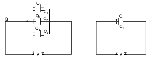
Consider three capacitors, having capacitances C1, C2, and C3 farad respectively, connected in parallel across a potential difference of V volts. In a parallel connection, the potential difference across each capacitor is the same but the charge on each is different.

Here, Q = Q1 + Q2 + Q3 = C1 V + C2 V + C3 V
= V (C1 + C2 + C3)
or Q/V = C1 + C2 + C3
But Q/V is the total capacitance CT of the combination of all the parallel capacitors connected in the circuit
CT = C1 + C2 + C3
Thus, capacitors in parallel are treated in the same manner as resistors in series. Therefore, the capacitors may be arranged in a parallel connection in order to obtain a larger value of capacitance than that will be achievable from individual units.
This article is a part of the Energy storage and reactive power compensation page, where other articles related to the topic are discussed in details.

