Cylindrical Capacitor
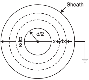
Two co-axial cylinders separated by an insulating medium is a basic cylindrical capacitor. A single-core cable is a practical example of a capacitor of this kind. The conductor (or core) of the cable is the inner cylinder while the outer cylinder is represented by the lead sheath which is at earth potential. Both cylinders have insulation in between.
Table of Contents
Mathematical interpretation of capacitance of the cylindrical capacitor
Let us consider a single core cable with a conductor diameter of d metres and an inner sheath diameter of D metres. Let the charge per metre axial length of the cable be Q coulombs and εr be the relative permittivity of the insulating material. Considering a cylinder of radius x metres.

According to Gauss’s theorem, the electric flux passing through this cylinder is Q coulombs. The surface area of this cylindrical capacitor is
= 2πx × 1 = 2πx m2
Therefore, electric flux density at any point P on the considered cylinder is given by;
Dx = Q/2πx C/m2
Electric intensity at point P is given by; Ex = Dx / ε0 εr = Q / 2 πx ε0 εr; V/m
The work done while displacing a unit positive charge from point P through a distance dx in the direction of the electric field is Ex dx. Hence, the work done in moving a unit positive charge from conductor to sheath, which is the potential difference V between the conductor and sheath, is given by;
V = d/2∫D/2 Ex dx = d/2∫D/2 Q / 2 πx ε0 εr dx = (Q / 2 π ε0 εr) loge D/d
Therefore,
Capacitance, C = Q/V = Q / (Q / 2 πx ε0 εr )loge D/d = 2 πx ε0 εr / loge D/d; F/m
= [2π 8.854*10-12 εr] / [2.3 log10 (D/d)] = εr *10-9 / 41.4 log10 (D/d); F/m
If the cable has a length of l metres, then the capacitance of the cable is
= εr l*10-9 / 41.4 log10 (D/d) Farad= 24 εr l *10-9 / log10 (D/d) pF
Some essentials
When the length and relative permittivity of the insulation/dielectric are given then the formulae to find the Capacitance is: εr l*10-9 / 41.4 log10 (D/d) Farad, which is explained above.
Charge on the capacitor
It can be calculated by Q = CV, where C is the capacitance and V is the potential difference.
The flux density of the dielectric
It can be easily computed by calculating the average radius which is x = 0.5 [D/2 +d/2 ] m
Therefore, flux density, D = Q/2πxl C/m2, where x is the average radius in meters and l is the length of the cylinder/ cylindrical capacitor.
The electric intensity in the dielectric
It can be equated by the formula E= D / ε0 εr V/m, where E is the electric intensity, D is the flux density in the dielectric and ε0 εr are absolute and relative permittivity.
Charging current per phase
It can be found out by Ic / phase = Vph / Xc , Where Vph = VL / 1.732
Ic/phase = 2πfC * Vph [Amps.], since Xc = 1 / 2πfC, where, f is the system frequency and C is the capacitance.
Total charging KVAR
The total charging KVAR = 3 * Vph * Ic, Where Vph is the phase voltage and Ic is the charging current per phase.
Factors affecting the capacitance of cylindrical capacitor
The factors influencing the capacitance are listed below:
Area of the cylinders: It is evident from the formula that the capacitance is inversely proportional to the log function of the ratio of outer cylinder dia to inner cylinder dia. Therefore, when the outer diameter decreases and the inner diameter increases, the capacitance will increase.
Length of the cylinder: Length of the cylinder directly impacts the capacitance as it is directly proportional to the length. Hence, the longer the length of the capacitor, the higher is the capacitance.
Size of dielectric: Though the formula for capacitance does not mention the size of the dielectric, it is evident that the closer the cylinders are, the higher the capacitance will be. Therefore, it can be inferred that the dielectric has to be lean for high capacitance.
Selection of dielectric material: The relative permittivity of the dielectric ɛr is directly proportional to the capacitance. Different insulating materials have different relative permittivity and therefore the capacitance can have an impact by the selection of dielectric material. A material with higher permittivity can increase the capacitance.
Applications of Cylindrical Capacitors:
- They are extensively used in power supply circuits to smooth and filter voltage spikes.
- For the purpose of impedance matching and tuning they are used in RF circuits.
- Used for applications that require high voltage and capacitance like pulsed power systems, and battery management systems.
- Employed as cable capacitors in high voltage underground transmission.

