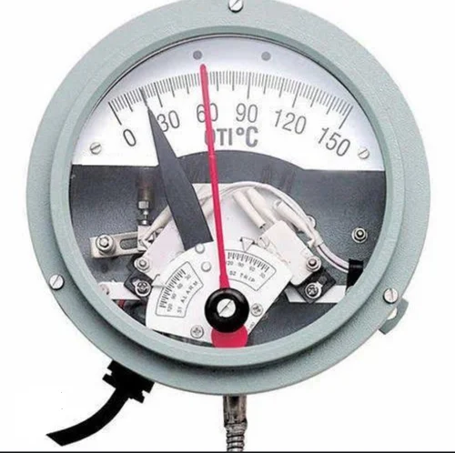
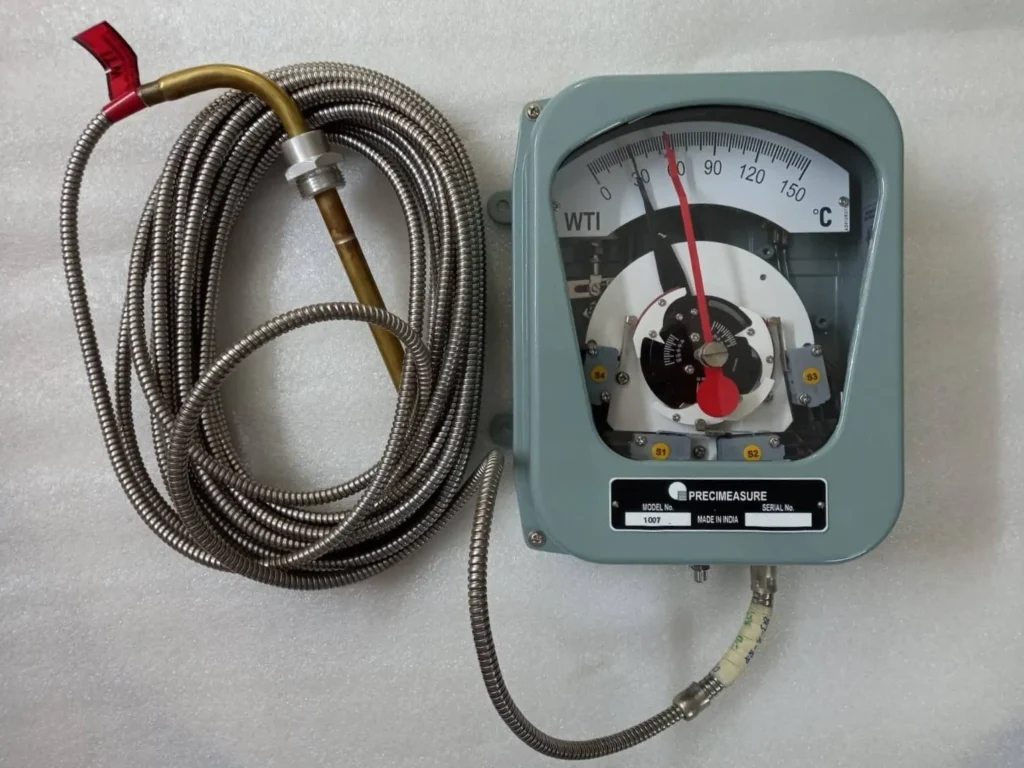
OTI is the oil temperature indicator of an oil-filled transformer. Since the transformer oil is also used for cooling purposes, the temperature of the oil gives out the internal thermal condition of the transformer.
WTI is the winding temperature indicator of the power transformer. The windings of the transformer are the heat source and its temperature is always higher than the oil. The winding temperature cannot be measured directly and so it is measured via the oil temperature and a current proportional heating element.
The temperature indicators are therefore essential to know about the internal condition of the transformer. It may also be noted that with the help of this indicator, both alarm and trip signals are generated when the temperature crosses the normal working limits.
Table of Contents
Functions of OTI & WTI
- Alarms can be raised as the transformer oil or winding reaches a preset temperature.
- Transformer cooling systems can be automated with them. As the temperature rises to say 60 degrees cooling fans can be turned ON utilizing the signals of indicators and similarly when temperature decreases fans can be turned off automatically.
- The temperature indicators can also be used to trip the transformer once the temperature crosses the safe limit.
Construction:
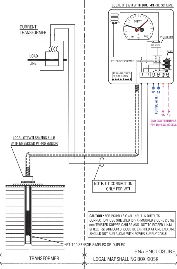
The device consists of a sensing bulb which is located on the top of the transformer. The bulb is linked to the instrument housing via flexible tubes. There are two capillary tubes one connected to the operating bellow and the other to the compensating bellow. Compensating below is used to compensate for the variation in ambient temperature. The indicator has four mercury switches that rotate with the indicating needle.
The device has two indicating needles one for the indication of temperature, which reacts to the expansion of fluid in the bellow and the other is a dummy one, which is pushed by the live indicator needle. The dummy needle stays at the maximum temperature as the temperature decreases the live needle falls back. These devices are also equipped with a power supply unit, PSU, and a communication control unit, CCU through which it can send output signals for remote temperature indication in the control room and SCADA integration is also possible.
Working principle:
Oil temperature indicator, OTI

The OTI indicator instrument is attached to a temperature-sensing bulb, which is installed at the top of the transformer in a thermometer pocket. As the temperature of the oil rises, the heat is applied to the bulb. The bulb being filled with other fluid, whose expansion is proportional to temperature rise, is connected to the temperature indicator with a capillary tube. The bulb transfers the heat of oil to the fluid inside. The heated fluid expands in volume. This expansion of the fluid turns the indication needle which is calibrated for the temperature range. Thus the oil temperature is indicated in the OTI dial.
Winding temperature indicator, WTI

In its process to mimic the loading in the transformer’s winding, the Transformer’s bushing CT is taken into use. The secondary current from the CT is fed to the heating element that surrounds the sensing bulb and as the loading on the transformer increases the secondary current of the bushing CT increases which heats a resistance connected to it, indirectly heating the bulb. The heat is then utilized to turn the needle of the indicator.
A very similar process to obtain the Winding temperature is having the resistor inside the measuring unit, the oil temperature expands the fluid in the capillary tube same as in the OTI measurement, and the additional heat of winding is mimicked by the resistor through the secondary current of CT. This heat from the resistor is added to the movement of the needle by a metal element which expands on heating.
As mentioned in the above process OTIs, WTI differs in just the bushing CT connection to get approximate values of winding temperature. The heat resulting from the approximate winding current is proportional to the expansion of the fluid in the capillary or the expansion of the metal element inside the measuring unit.

The indicator’s plate has four mercury switches two for alarm and two for trip. As the needle rotates the plate also rotates and at a determined temperature the mercury switch sends an alarm/tripping command as configured.
Mostly alarm contacts can be configured in the range of 50-100 degrees Celsius and trip contacts can be configured between 60-120 degrees Celsius.
Similarly, the control of the cooling system can also be configured with the dynamic indicator dial.
The starting of cooling fans is normally automated with the winding temperature indicator. As the temperature of the WTI is more than a preset value, the cooling fan starts, and as it reaches below a certain value the fan stops.
It may be noted that some fans or groups of fans remain on standby. When the temperature does not fall back and increases say from 60 degrees C to 65 degrees C, the other group of fans also starts operation by automation and it is linked to WTI.
For Transformers with pumps for oil flow, the pumps are also automated which means the starting and stopping of the pumps are controlled by the temperature in the WTI.
Maintenance
The instrument being a mechanical device though is equipped with an IP55 rating, maintenance is required for calibration of the OTI and WTI indication.
CONCLUSION
Currently, many new technologies are in the research stage for OTI and to model the winding temperature of a transformer accurately among them are the use of optical fiber and thermal sensors. However, due to the very high cost, it is currently not feasible and also retrofitting of such a type is not an easy task.
The winding is a delicate part of the transformer that handles very high voltages and hence it is not feasible to directly attach a temperature sensor to it. However indirect method is thus applied to measure and indicate the transformer’s winding temperature. However, due to natural circulation, the oil moves to the top hence for OTI the top thermometer pocket gives a good indication.
FAQ’s
What are the OTI and WTI settings in the transformer?
The most common OTI setting of the alarm is mostly 80 degrees C and the trip is set to 90 degrees C. For WTI, the setting for the alarm is 85 degrees C, and the trip is 95 degrees C. This is because the temperature rise limit in most of the oil-filled transformers is limited to 30-55 degrees above ambient temperature.
Which is greater OTI or WTI?
The winding temperature is always greater as the heat is developed in the winding itself. The temperature of the oil is because of the transferred heat due to convection, which is always lower than the source.
What does the red needle indicate?
The Red needle in the OTI and WTI indicates the highest oil temperature and winding temperature attained in the day. The needle has to be reset to get the next day’s maximum temperature.
At what temperature do the cooling fans start?
At 65 degrees C of the WTI, the cooling fans start operation.
This article is a part of the Transformer page, where other articles related to the topic are discussed in details.

