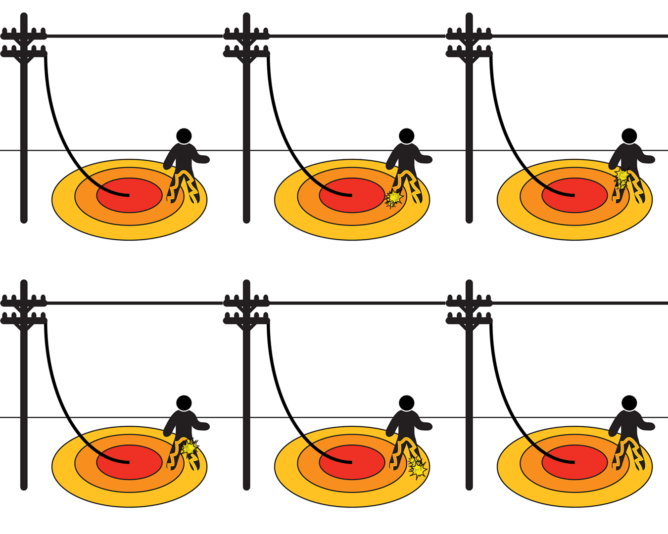
Step potential and touch potential are very essential factors in the designing of the earthing system of any substation. Step potential and touch potential also decide the overall safety of personnel working in the substation. As for humans, 25mA current can prove fatal hence calculation of step potential and touch potential is very important.
STEP POTENTIAL:
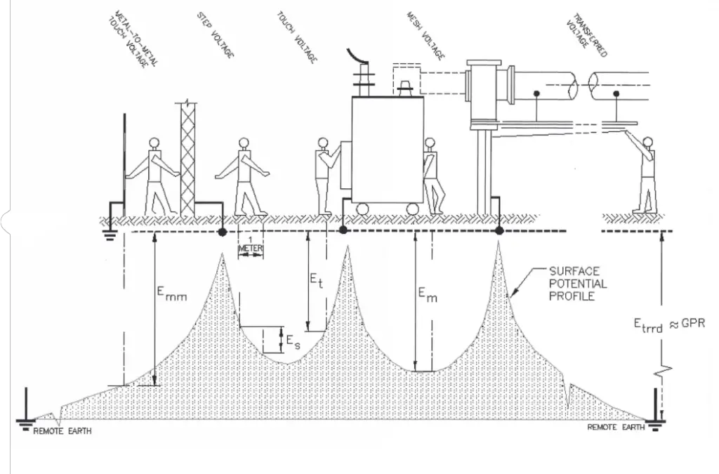
When a conductor is grounded or a fault occurs in a substation or a transmission tower, the potential that is developed between two points in the ground because of variation of soil resistivity is known as step potential.
Table of Contents
As the fault occurs, the current will enter the earth. Based on the varying distribution of soil resistivity, the voltage distribution will take place. The voltage drop in the soil surrounding the grounding system will present a hazardous situation for any personnel standing in the vicinity. Personnel stepping in the voltage gradient will be subjected to a difference in potential between his/her feet, which will result in the flow of electricity through them.

To avoid the situation proper calculations must be carried out by the utility engineers. Any personnel in the zone must be wearing the safety shoe electrical grade as it gives millions of ohms resistance when dry. Instead of taking big steps out of the zone, it is advisable to move in little steps, the heel must not move ahead of the toe.
TOUCH POTENTIAL:
In case of an electrical fault, current will pass from the metallic object/ conductor to the ground. Any person touching the metallic object in the vicinity of the ground potential rise (GPR) will be subjected to the touch potential.
It is basically because of the difference in potential of the ground network and the personnel touching the metallic part, current will pass through the personnel to the earth.

Careful analysis is required to determine the acceptable fibrillation currents that a body can withstand if a fault is to occur. Engineering standards use a one-meter (3.28ft) for calculating touch potentials. A two-meter (6.54 ft) reach is also used when two or more objects are inside the GPR event area.
Calculation of Step Potential and Touch Potential
When two points are connected in series by an external circuit, the current in the circuit is a function of voltage between two points and the external circuit’s resistance. Here the external circuit is human body connecting two points on the ground.
The current in this case has two parallel path one through the ground and other through the human body. As the fault current level is very high and allowable current through the body has to be in miliampere level for safety, the impact of the human body on the potential difference is therefore negligble.
The touch resistance RF between human feet and ground and the human body resistance RB is connected in series, then the permissible step potential US between the two feet is given by:
US = [ RB + 2 RF] Ik
Where Ik is the allowable body current.
Similarly, when a person on the ground, touches a grounded conductor, the touch resistances of the two feet with the ground are parallel, therefore the permissible touch potential, UT between the hand and feet is given by
UT = [ RB + 0.5 RF] Ik
Where Ik is the allowable body current.
Usually, the human feet is considered as a round plate with a radius b (in cm) in uniform soil, then RF can be calculated by
RF = ρS / 4b
where ρS is soil resistivity (in Ω m). Usually, b = 8 cm, and then the touch resistance of one feet is approximately 3 ρS (in ohms).
Now the equation for body current through a human body for a very short period of time can be given by
Ik2 * t = K, where Ik is the current in amps and K is the co-efficient of energy which is the function of body weight. For 50kg, K=0.0135 and for 70kg, K=0.0247 and t is the time period in second.
For 50kg body weight the allowble body current is
IK50 = 0.116 / √t
For 70kg body weight the allowble body current is
IK70 = 0.157 / √t
Now, the maximum permissible step potential and touch potential, US50 & UT50 respectively for a 50 kg considering body resistance of 1000 ohm can be obtained by
V R I
US50 = ( RB + 2RF ) IK = ( 1000 + 6 ρS ) 0.116 / √t = ( 116 + 0.7 ρS ) / √t
UT50 = ( RB + 0.5RF ) IK = ( 1000 + 1.5 ρS ) 0.116 / √t = ( 116 + 0.17 ρS ) / √t
Similarly, we can obtain the maximum permissible step potential and touch potential US70 & UT70 respectively for a 70 kg human body
US70 = ( RB + 2RF ) IK = ( 1000 + 6 ρS ) 0.157 / √t = ( 157 + 0.942 ρS ) / √t
UT70 = ( RB + 0.5RF ) IK = ( 1000 + 1.5 ρS ) 0.157 / √t = ( 157 + 0.2355 ρS ) / √t
Influence of Resistivity of Surface Soil Layer on step potential and touch potential
According to the above equations, the permissible step and touch potential are a direct function of the resistivity of the surface soil layer, ρS which can be altered by introducing highly resistive surface soil layer.
Therefore, adding a high-resistive layer on the ground surface also restricts the fault current from flowing into the surface layer without raising surface potential. With this addition of high resistive surface layer, the touch resistance also increases, minimizing the current flow through the body.
In substations, usually a layer of gravel or asphalt concrete pavement with a thickness of 15–38 cm is laid on the surface of the ground so that even on rainy days, the gravel or asphalt concrete can keep a resistivity of 5000 Ω m.
It is to be noted that only surface concreting shall never be used to increase surface resistivity as normal concrete absorbs water, and on rainy days the resistivity will drop to dangerous levels.
The touch resistance RF is a function of ratio of the resistivity between high resistive layer and the soil layer. The thickness of the high resistive layer also impacts the touch resistance RF.
As per recommendation from IEEE Std80-2000, Touch resistance RF can be written as
RF = CS ρS / 4b
where CS is the correction coefficient of the foot grounding resistance in the high resistivity layer.
The correction coefficient can be calculated using the following empirical formula
CS = 1 – {a(1- ρ/ ρS)} / {2hS + a}
where hS is the thickness of the high-resistivity surface layer (in m), ρS is the resistivity of the high-resistivity layer (in Ω m), ρ is the resistivity of the uniform soil under the high-resistivity layer (in Ω m). a is a constant which is equal to 0.09m.
After accounting the high resistive surface layer, the formula for calculating the maximum allowable step potential and touch potential, US50 & UT50 respectively for a 50 kg human body changes to
US50 = ( RB + 2RF CS ) IK = ( 1000 + 6 ρS CS) 0.116 / √t = ( 116 + 0.7 ρS CS ) / √t
UT50 = ( RB + 0.5RF CS ) IK = ( 1000 + 1.5 ρS CS) 0.116 / √t = ( 116 + 0.17 ρS CS ) / √t
Similarly, the formulas step potential and touch potential for a 70 kg human body change to
US70 = ( RB + 2RF CS ) IK = ( 1000 + 6 ρS CS) 0.157 / √t = ( 157 + 0.942 ρS CS ) / √t
UT70 = ( RB + 0.5RF CS ) IK = ( 1000 + 1.5 ρS CS) 0.157 / √t = ( 157 + 0.2355 ρS CS ) / √t
MITIGATION TECHNIQUES:
Mitigation of the step potential and touch potential is usually accomplished through one of the three major techniques:
Reduction in Ground resistance of the system.
The step potential and the touch potential can be greatly reduced by lowering the earth resistance. Various process of reduction in ground resistance are chemical charging in the soil, introducing moisture in the soil, etc.
Proper placement of grounding conductors.
Placement of grounding conductors effects the grounding resistance greatly. As we reduce the space between the grounding conductors, by adding more, the entire grounding system will act as a metal plate and the dangerously high step potential and touch potentials can be fixed.
The addition of high resistive surface layers.
By addition of a high resistive layer of aggregates 15-38cm thick we can greatly reduce the occurrence of the high step potential and touch potential. This is because the high resistive surface layer resists the fault current flow into the surface layer there by increasing the touch resistance.
CONCLUSION
We now understand the potent risk of step potential and touch potential which can cause electrocution. Therefore it is equally important to take measures to mitigate the high rise of voltages. Equipment shall therefore be marked or properly fenced so that they remain only accessible to trained personnel with proper safety gear and no general public.
This article is a part of the Safety and Earthing page, where other articles related to topic are discussed in details.

