RESTRICTED EARTH FAULT PROTECTION
The most vital and important protection for a transformer is the biased differential relay protection of the transformer, which is discussed in detail in previous articles. It provides excellent protection against phase-to-phase faults and phase-to-earth faults within the differential zone of protection.
Table of Contents
It covers 80% winding from the bushing, however, it is not capable of providing protection against a single phase-to-earth fault near the neutral in a star-connected transformer with solidly grounded neutral because of its biasing feature. To address this constraint Restricted Earth fault protection is used.
Restricted earth fault protection is basically earth fault protection and since the relay’s reach is restricted to the winding of the transformer, basically from the bushing turret to the neutral of the star-connected transformer with solidly grounded neutral. Hence, it is termed restricted earth fault protection. It is a complementary protection to differential protection as this protection is also based on the Merz-price methodology.
TYPES OF RESTRICTED EARTH FAULT
LOW IMPEDANCE RESTRICTED EARTH FAULT PROTECTION
Low impedance REF relay is a numerical relay that has a percentage bias function like a differential relay. This function facilitates the use of different ratio CTs in the line/turret and neutral. The ratio differences are taken care of in the Low Impedance Relay itself through the scaling factor which has to be selected in the relay. It has accelerant sensitivity and stability against CT saturation due to heavy-through transient faults by automatically selecting the appropriate percentage bias.

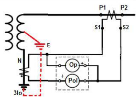
Although actual Low impedance REF may differ in algorithm from relay make to make in general, but Low Impedance REF protection commonly uses a directional element that compares the direction of an operating current derived from the line/turret-end CTs, with the polarizing current obtained from the neutral CT.

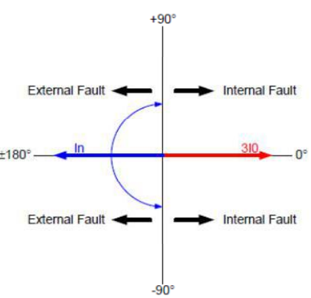
The directional element compares the angular difference between the polarizing current (3Io derived from line/turret CTs) with the operating current from Neutral CT and indicates forward (internal) fault location when the angular difference is < 90 degrees or reverse (external) fault location if the angular difference is > 90 degrees. The forward/internal indication occurs if the fault is within the protected winding, between the line/turret-end CTs and the neutral CT.
HIGH IMPEDANCE RESTRICTED EARTH FAULT PROTECTION
The operating principle of the high impedance REF is to balance the sum of the residual phase currents with the output of a current transformer in the neutral. There are four CT connections where the transformer is solidly earthed significant part of the winding is protected. For external faults, the secondary current of the affected line/turret CT is balanced against the secondary neutral current in opposition, causing no current to flow in the High impedance REF relay thus this protection is stable.
However, for internal Earth faults near the neutral, the REF relay will sense the secondary fault current through the neutral via NCT and operate. This protection is widely used as it has better sensitivity against CT saturation.
WORKING PRINCIPLE:
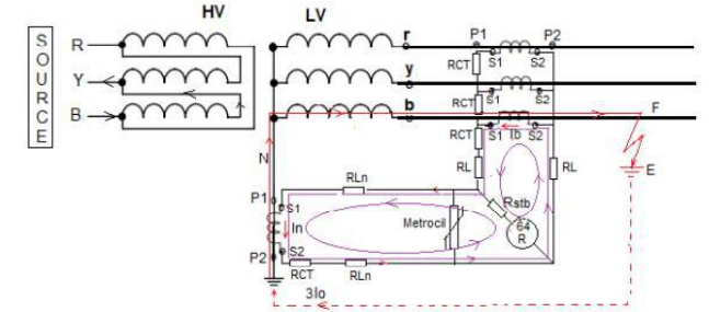
As per the High Impedance Restricted earth fault protection scheme, the secondary earth fault current ‘In’ entering the source through the neutral is balanced against the secondary current of the affected CT. All the secondary windings of the phase CTs (line/turret) are connected in parallel i.e. all the S1 terminals and all the S2 terminals are connected in parallel to form the residual Circuit and are balanced against the secondary current of the Neutral CT.

In case of through earth fault, the direction of the secondary loop current of ‘3Io’ from the affected phase line/turret CT would be from S2 to S1 and the secondary of the Neutral current ‘In’ entering the Transformer through Neutral in the opposite direction will have the direction from S1 to S2. Since the loop currents are in opposition to each other therefore shall cancel each other and there shall not be any current through REF relay 64 R.
Although the stabilizing resistor helps the relay not get energized in case of external faults of the protected zone. Let us discuss this concept. Suppose there is an external earth fault and because of that high amount of fault current will flow through the line CT’s secondary because of this high current, the stabilizing voltage in the CT may become adequate to cause the REF relay to mal-operate. It is for this reason the stabilizing resistor is used with the REF relay so that it will not react to any external earth faults.
The % Bias Differential relay with a 20% bias setting and with an operating current setting of 0.2PU can cover 80-85% of the winding only. High Impedance REF protection takes care of the faults between phase winding and earth against the unprotected 20% of the winding close to neutral.
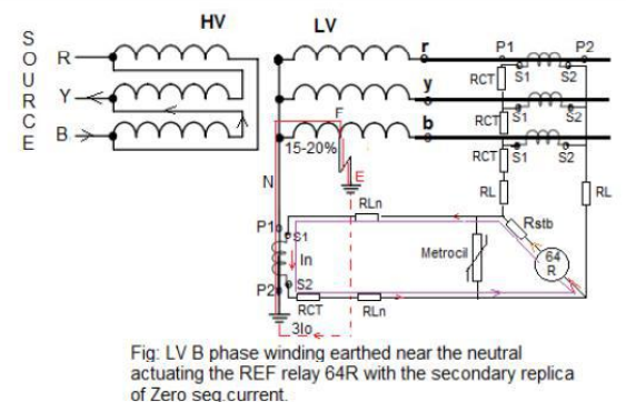
In a star-connected transformer, the voltage also reduces in proportion to the remaining turns (distance) from the neutral. Thus, whenever the Phase to Earth fault occurs within 20% distance from the neutral, the driving voltage of the Earth fault current is very low. The secondary replica of this low earth fault current (3Io) is sufficient to activate the REF relay 64 R.

LV B Phase to earth fault occurs at a location F of the winding in the vicinity of 15-20% of the winding from the neutral. The zero sequence earth fault current (3Io) will follow the path shown in red colored dotted lines and will enter the source through the Neutral N secondary replica of zero seq. Primary Earth fault current (3Io) is (In) in the secondary and is in the opposite direction of it (as per characteristic of a CT).
This ‘In’ shall circulate in the loop actuating the REF 64R relay and in turn give a trip command to the master trip relay of the associated Circuit breaker.
FAQ’s
What is the difference between earth fault and restricted earth fault?
Earth fault is a fault that includes phase and ground and is an external fault. Restricted Earth Fault is also an earth fault which is an internal fault restricted within a zone.
What is the cause of restricted earth fault?
Restricted earth fault is majorly caused by winding insulation failure near the neutral point inside the transformer which results in a small fault current that remains undetected by differential protection because of the bias feature. The restricted earth fault protection is therefore an inexpensive solution to the problem.
Why CT are not connected in delta configuration for restricted earth fault protection?
Connecting the CTs in delta configuration will nullify the zero sequence component, hence it should be noted that for restricted earth fault protection the CTs should never be connected in delta configuration.
This article is a part of the Protection System, where other articles related to the protection of electrical equipments are discussed in details.

