POWER CLAMPS
Electrical energy flows through many equipment and various lines to reach the end consumer or load. In this process, it requires many terminations of conductors to all the equipment it passes through.
Table of Contents
This termination is made possible through the use of various clamps and connectors that we will discuss below. The clamps and connectors need to be mechanically strong and stable, so it is duly designed to handle the electro-mechanical stress and thermal stress resulting from any short circuit faults in the system.
TYPES OF CLAMPS
PG CLAMPS:
PG clamps or parallel groove clamps are a type of power clamps used for the connection of any parallel conductors that may run short of reaching the termination point. PG clamps have two grooves equidistant from its center. The connector and the clamping part are usually made of all alloy material as per standard specifications. In India, we follow IS-617. The clamp’s size varies depending on the conductor type.

TEE CLAMPS:
These power clamps are used for the connection of two conductors which are to be connected perpendicularly. It is widely used in busbar droppings. Tee clamps are also known as compressed jumper clamps as tee clamps are also utilized in jumpering of the electrical networks. The size of tee clamps varies depending on conductor sizes.
Tee clamps available in the market are Zebra Run Zebra Drop, Panther Run Panther Drop, Zebra Run Panther Drop, etc.

L TYPE OR UNIVERSAL CLAMPS:
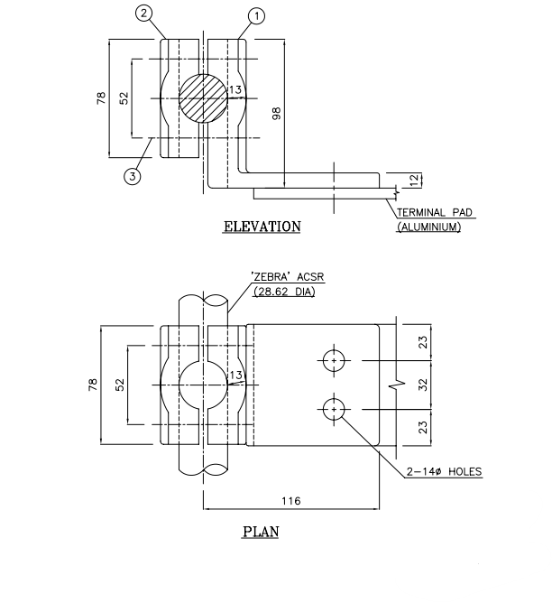
L-type clamps are a type of power clamps used in connection with Lightning arresters. These have a clamping part through which the conductor runs and a terminal part that is used for the termination of electricity to equipment such as LA. Their sizes vary depending on the conductor size as well as the terminal equipment size.

PAD CLAMPS:
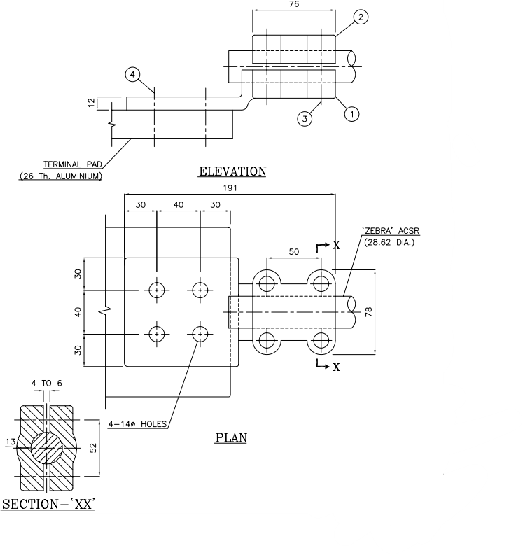
Pad clamps are a type of power clamps, used in equipment termination such as circuit breakers. These clamps generally have an aluminum pad and an alloy clamping part. The pad usually has 4 nos. of drilled holes for connection to equipment via which termination is possible. The clamping part successfully holds the conductor in the groove and is tightened via bolts and washers.

SPACER CLAMPS:
The spacer clamps are power clamps, extensively used in buses where twin conductors or four conductors are used. They are also used in transmission lines. This is used so that the subconductors in the bundle do not clash with each other in high wind and to avoid the pinching force in the conductor during any short circuit. The spacing between the subconductors of a phase is normally between 250 and 450mm. The spacer span depends on the tower span and short-circuit current value. Normally we take between 2 to 4 meters.

SINGLE TENSION/SUSPENSION HARDWARE FITTINGS:
It is used in transmission lines or buses to hold a conductor with disc insulators. The conductor is crimped with a crimping tool to the tension clamps. It has a D-shackle which connects to the ball link of the insulators to the tower. The yoke plate connects the insulator string to the bolted-type tension clamps that hold the conductor.
In suspension-type fittings the tension clamp is replaced with a suspension clamp, envelop type and in place of the D shackle it uses a ball hook that can hold the arcing horn.

For the twin conductor setting both use the D-shackle for connection with the tower.
REQUIREMENTS
- All power clamps must use all alloy 4600 (A6) as per IS-617
- All bolts, nuts, and plain washers must be hot-dipped galvanized and the spring washers must be electro-galvanized.
- Bolt tightening torque must be 400-600 kg-cm as recommended for M-12 and M16 types.
- The resistance of the clamps should be within 10% of the resistance of a conductor 1.25m long without the clamp.
- Maximum allowable temperature rise should be 35 degrees Celsius above 50 degrees ambient temperature.
- Clamps should be designed to support the conductor’s ampacity as for zebra it should withstand 2000 A of continuous rated current.
- All the sharp corners shall be smoothly rounded.
This article is a part of the Cables and Conductors, where other articles related to the topic are discussed in details.

