OVER FLUXING PROTECTION OF TRANSFORMER
In transformer design practice the rated value of flux density is 1.7 to 1.8 Tesla. However, the saturation flux density of the CRGO steel sheet is of the order of 1.9 to 2.1 Tesla. This means the transformer core can handle a flux density of 1.1 times the rated.
Table of Contents
OVER FLUXING
Over-fluxing is, therefore, a situation when the flux density in the transformer’s core exceeds the rated value.
Flux density is a function of the voltage and frequency. It is proportional to the voltage and inversely proportional to the frequency. Therefore, over-fluxing can occur due to a rise in voltage, a dip in frequency, or both.
Over fluxing is primarily faced in the generating transformers more than the step-down transformer as the voltage and the frequency remain almost constant on the transmission side. However, it can cause potential harm to any transformers.

PHENOMENON:
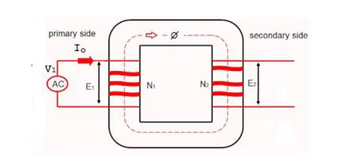
Whenever, there is an overvoltage and when frequency remains constant, the transformer core is subjected to a high flux in order to be able to sustain the applied high voltage. The voltage and the flux in a transformer are related by the equation
V = 4.44Fm f N, this can be written as
Fm = V/ 4.44fN
Where V is the rms value of the voltage
F is the frequency
And N is the number of turns in the winding.
Power transformers by design, operate at the knee of the saturation curve at normal voltage. Hence any increase in the applied voltage and consequence increase in the flux density drives the transformer into deep saturation. The transformer, therefore, draws an excessive magnetization current. Hence, this condition is described as over-excitation. It can also be observed that overexcitation can also occur due to low-frequency operation of the transformer at rated voltage. Therefore, to keep the working flux within the permissible designed limit, the V/f ratio must not exceed the permissible limit.
CAUSES OF OVER FLUXING:
- Sudden load rejection may cause over voltage and it in turn causes over-fluxing of the transformers.
- Generation at low frequency causes over-fluxing of transformers at rated voltage.
- Lightly loaded transmission lines are a common cause of over-fluxing. As in lightly loaded transmission lines, the capacitance increases the line voltage and this high voltage causes over fluxing of the transformers.
- Improper shunt compensation may also be a cause that gives rise to the voltage of the lines which causes over fluxing of transformers.
EFFECTS OF OVER FLUXING:
In normal conditions, the magnetic flux is routed through the gaps and remains confined in the core of the transformer because of the higher permeability of the core material than the surrounding material.
As the flux density in the core increases and crosses the saturation level, the magnetic flux then reaches the other structural steel parts of the transformer which are not designed to carry this flux, starts heating up rapidly.
Unplanned path of the flux linking to the conductive loops inside the transformer thus induces circulating current in the loops and a rapid temperature rise is observed in this situation.
At this high level of excitation, all the metals inside the transformer face discoloration due to high heat, the paints start forming blisters, the insulation oil starts to break down with gas formation and other contaminants may include metal parts.
However, transformers can withstand this over-fluxing for a short time but any continuation of it weakens the electrical and mechanical properties of the core, bushing leads, and core laminations.
Other effects include the rise of core losses and hotspot creation etc.
OVER FLUXING RELAY
Over-fluxing is, therefore, an important concern, especially for generating transformers. Excessive excitation current leads to overheating of the core and unlaminated metal parts of the transformer. It causes damage to the insulation and leads to permanent failure. IEEE recommends that the transformer should be capable of operating continuously above the rated secondary voltage at no load without exceeding the thermal limits. This requirement applies to any tap at the rated frequency.
Generator unit transformers are subjected to varying frequencies during the acceleration and deacceleration of the turbine. Under these conditions, the voltage-to-frequency ratio shall not exceed 1.1 times the rated ratio.
It is to be noted that 1.1 times the rated ratio of V/f is on a p.u basis.
Let us suppose there is a 132KV transformer and it has over fluxing relay protection
The primary voltage is rated at 132KV and the frequency is 50 Hz.
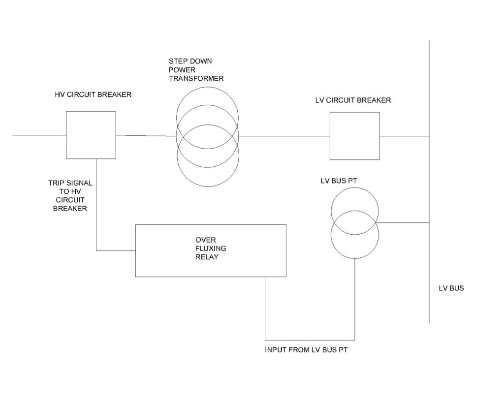
The over fluxing relay utilizes the voltage from the Potential transformer’s secondary and hence at the secondary of the PT the rated voltage will be 110
Therefore V/f in this case is 110/50 which is equal to 1/1=1 p.u
Let us suppose the voltage at primary has increased to 146KV and frequency to 50.1 Hz
Then, PT secondary voltage will become 146*110/132 = 121.6V (using the unitary method).
Therefore, the ratio V/f becomes = (121.6/110) / (50.1/50) =1.12
At this ratio of 1.12, the over-fluxing relay will pick up and since these relay’s characteristics are inverse, the over fluxing relay will generate a trip command after some time delay according to its characteristics curve.
If the primary voltage is maintained at 146KV and 50.1Hz for some time then the over fluxing relay will trip the transformer protecting it from over-fluxing.
Generally, the over fluxing relay is kept inverse because transformers have a short time withstanding capacity of over fluxing and avoid unwanted tripping for a slight increase in the ratio V/f for a very short time. The ratio V/f is generally set at 1.10. The faster the ratio increases the faster the tripping of the transformer.
However, this relay initiates an alarm for the operators to act as soon as the ratio is touched.
In the case of step-down transformers with tap changers, it is possible to lower the tap from the nominal position which will decrease the primary winding turns thereby lowering the voltage and hence reducing the over-fluxing.
However, since the over fluxing relay takes the input of voltage parameters from PT secondary, lowering the tap of the transformer does not seem helpful as tap operation won’t impact the HV voltage as seen from the HV side PT. The over fluxing relay will anyway initiate the trip if the ratio V/f increases. It is to address this reason, the over fluxing relay is given input from the secondary side of the transformer to take care of the tap change consequences. That means the voltage input to the over fluxing relay of the transformer will go from the transformer’s LV side PT secondary and not the HV side.

FAQ’s
What is over fluxing?
Over-fluxing is the result of increased flux density compared to the rated flux density that a transformer is designed to handle. The excessive flux density results from increased voltage, low frequency, or both. Over-fluxing causes the flow of current in the metallic parts of the transformer increasing loss and heat. This heat can melt the critical internal parts resulting in internal electrical and structural faults. Over fluxing relay is used to counter this phenomenon.
What is the ANSI code for OVER FLUXING RELAY?
The ANSI code for over fluxing relay is 24.
This article is a part of the Protection System, where other articles related to the protection of electrical equipments are discussed in details.

