OLTC
OLTC or On-load tap changer is a device that is used for voltage regulation of a transformer without any interruption in the power flow to the load. Tap changing basically alters the turns ratio of the transformer thus regulating the voltage.
Table of Contents
The main feature of the On-load tap changer is that the tap-changing process does not require the transformer to be put out of service. The tapping is usually provided on the HV winding of the transformer because the high voltage side has less current and hence the size of contact leads will also be small.
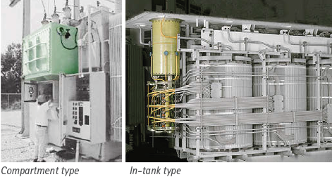
Tap changers are equipped with a selector switch and a motor mechanism in the same housing and can be operated locally or remotely via OLTC pannel. Manual changing of the tap via a handle is also provided in case the motor malfunctions. The selector switch allows the operator to choose the required tap position by shifting up or down as per the prevailing operating conditions. The motor mechanism or manually controlled shaft is rotates several turns to physically shift the tap to the selected position.
PRINCIPLE OF SWITCHING :
The turns ratio of the transformer is changed either by the increase or decrease of the number turns from the high voltage winding of the transformer. Therefore, for cutting short or adding more, a regulating tap winding is installed in the transformer which is also connected to the on-load tap changer.
The addition or subtraction of turns while the transformer is energized breaks the connection to load momentarily while the switching is in progress. Therefore making of contacts before breaking and not otherwise is the design fundamental of all On-load tap changers.
An element of resistance or reactance of single or multiple units forms the impedance that adjoins the nearest taps intended while transferring load from one tap to the other without any interruption or load current decay.
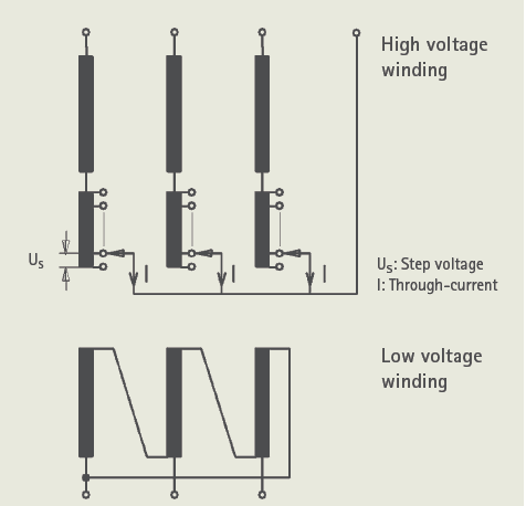
When both taps are engaged, the transition impedance limits the circulating current (IC) for that short time span.
The potential between the adjacent taps is called the step voltage. It is expressed in the percentage value of the rated voltage of the transformer. The normal range is 0.8 – 2.25%. The most common step voltage is 1.25% of the rated voltage and ±10% voltage regulation range. The total number of taps in this case will be = (Total voltage range / Step voltage)+1
= (20 / 1.25) + 1 = 17 number of taps, 9 being the nominal tap.
[±10% voltage regulation range means total voltage regulation range of 20%]
This value necessitates the fine output voltage regulation. The main components of an OLTC are tap contact systems that carry, make, and break the current, the transition impedances for smoothing the operation, gears, springs, and a drive mechanism for physical turning and engaging.
RESISTOR TYPE OLTC
The resistor type OLTC essentially includes a transition resistor which limits the circulating current during the tap-changing process. The on-load tap changer with higher voltage and rating basically uses a tap selector which selects the intended tap and a diverter switch that operates to change the tap position. However, for lower ratings, both functions are merged in a selector switch.
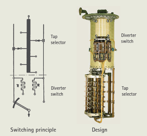
In the high-voltage OLTCs, the tap changing consists of two steps. Firstly, a tap is selected in the tap selector by the action of the drive mechanism either locally or remotely as shown in Fig (a-c). Then only the diverter switch operates to transfer the load current from the tap in operation to the preselected tap as shown in Fig (c-g) by spring action.
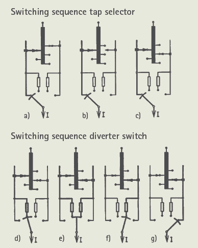
The tap selector is operated by the movement of the gear arrangement directly from the drive mechanism manually with the handle or via the motor which then charges the spring. The spring then, in a short time period, independently operates the diverter switch by discharging.
The gear mechanism ascertains that the tap selection process precedes the diverter switch operation. The complete operation of the diverter switch takes between 30 and 60 ms.
Transition resistors are placed in the circuit as shown in Fig (d-f) which are charged only for 20–30 ms, it means that the resistors of these OLTCs can be designed for a very brief time capacity, also with a relatively small resistive material. The total time of operation may range anywhere between 3-10 s subjected to design.
REACTOR TYPE OLTC
The reactor-type OLTCs include an inductor element center tapped for transition impedance for limiting the current during the switching operation. In reactor-type OLTCs, the reactor is designed for continuous loading because the adjoining position of the reactor is the service position.
Switching used for reactor oil-type OLTCs are:
- Selector switch (arcing tap switch)
- Diverter switch (arcing switch) with tap selector
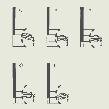
The center-tapped reactor connected between two tap leads allows the sharing of current momentarily but with transition impedance to limit the circulating current.
Only the selector switch type reactor OLTCs are in production while the others are soon going to be obsolete.
This article is a part of the Transformer page, where other articles related to the topic are discussed in details.


Very clear and easy explanation of OLTC functionality. Maintaining voltage stability without interrupting power is critical in modern power systems. Companies like EMR Global, with decades of expertise in OLTC manufacturing, spares, and services, play a key role in improving transformer reliability and long-term performance across utilities and industries.
Thank you!
Clear OLTC explanation. Quality tap changer parts and retrofit services from EMR Global help utilities keep voltage stable without interrupting supply.