CT SATURATION:
In the ideal scenario of the operation of a current transformer, the secondary current of the CT, (Is) is directly proportional to its primary current (Ip). However, in the case of saturation of the CT, the proportionality does not remain the same. Let us discuss why.
Table of Contents
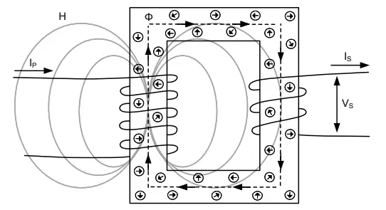
The CT’s iron core has fixed numbers of magnetic dia-poles. Let us consider them as molecular magnets. Ideally, these magnets are randomly arranged in polarity throughout the core as shown below.

When the alternating current Ip flows through the primary winding of the CT, it generates the magnetic field ‘H’. The strength of this magnetic field affects the magnet in the core and causes it to be aligned in the direction of the magnetic field to produce the magnetic flux Φ.
The more current Ip that flows through the primary winding, the stronger the magnetic field H becomes, and more of the magnets are lined up. According to this analogy, the number of magnets lined up at a given time is the flux density ‘B’.
When all these magnets are aligned in the same direction of the magnetic field, the maximum flux density of the core of CT is reached. Therefore, the CT core is said to be saturated.
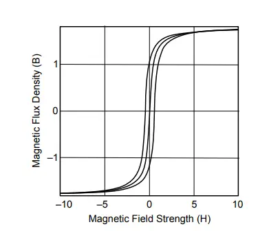
THE B-H CURVE
The relationship between the magnetic field strength H and magnetic flux density B is given by the B-H curve.

Different types of core materials have different B-H curves, it depends on the ability of the material to support the magnetic field.
This magnetic behavior affects the ability of the CT to reproduce the secondary current. The change in flux caused by the changing direction of AC induces a voltage Vs in the secondary. This voltage Vs generates the current Is through the connected circuit.
When the core reaches maximum flux density, it is fully saturated as there are no more molecular magnets left to change direction. This causes the voltage Vs to drop to zero and the current Is ceases to flow in the secondary.
TYPES OF CT SATURATION
SYMMETRICAL CT SATURATION:
Symmetrical CT saturation results from a symmetrical current in the primary that is too large for the CT core to handle for a given burden.
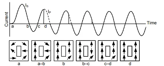
Ideally, before the current is applied, the magnets in the core are aligned in random directions. As the primary current Ip starts to flow in the first positive half cycle, the magnets in the core line up in the positive direction. Because of this change in flux, the Is in secondary is proportional to Ip. Just at this point, all the magnets available are lined up in the positive direction and the core has reached the maximum flux density, and saturation.
At this point, even if the Ip continues to flow, there is no more change in flux, and Vs and Is drop to zero. Is stays at zero until the Ip begins to flow in the negative direction, reversing the magnetic field. This negative flow causes the magnets to align in the negative direction, the change in flux generates voltage Vs and Is starts to follow Ip until all magnets are aligned in the negative direction causing saturation and Vs and Is again drops to zero.

The above figure shows that in the second cycle, the lower magnitude of current, generates a weaker magnetic field, requiring less flux density or less involvement of magnets to replicate the primary current Ip. Because of fewer involvement of magnets the Is can follow Ip for a longer time until all the magnets get aligned.
However, in the third cycle, the Ip has been lowered to the point where the CT core does not saturate and the Is correct replicates the Ip the entire cycle.
ASYMMETRICAL CT SATURATION
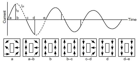
This type of ct saturation basically results from a high level of DC offset in the primary current of the CT. Here the current peaks are not symmetrical to zero line. DC offset is when there is more area under the curve above the zero line than below it.

The figure shows how the DC offset causes the CT to quickly saturate. From points a to b, magnets are all lining up in the positive direction and the CT has not saturated. When Ip becomes negative, from points b to c, magnets start changing directions and lining up in the negative direction.
Because there is such a small amount of area under the curve between Points b and c, not very many of the magnets have lined up in the negative direction when the Ip current goes back above the zero-crossing (Point c) and they are forced to start lining up in the positive direction again.
Finally, at Point d, all of the available magnets are lined up in the positive direction and the core saturates. Thus, the DC offset, and not the magnitude of the fault current itself, is what causes the saturation. The fact that Ip is not below the zero-crossing long enough to reset the magnets in the opposite direction is what causes the ct saturation to occur.
It should be noted that the amount of time the CT is saturated is less with each cycle as the dc component decays.
CONCLUSION
Thus, the magnetic behavior is the integration of the volt-time area. With a fixed burden, the current is directly proportional to voltage. The amount of flux that accumulates in the core is directly proportional to the area under the voltage or current curve.
Any given CT can handle some maximum amount of flux before it saturates. This limit is defined by the symmetrical sine wave with a fixed voltage magnitude and a fixed area under the curve in both positive and negative directions. If the CT waveform does not exceed this volt-time area, the CT will not saturate.
The DC offset of the asymmetrical current results in the accumulation of positive volt-time area that eventually reaches the maximum that the CT can handle at point d where the saturation occurs.
Time taken by the CT to saturate can vary depending upon the current magnitude, DC offset, X/R ratio, burden, and remanence.
Remanence is the flux density remaining in the CT core after the primary is disconnected.
This article is a part of the Transformer page, where other articles related to the topic are discussed in details.

