CARRIER AIDED PROTECTION
The main aim of electrical power transmission is to maintain an uninterrupted power supply of electricity to all consumers. Electrical faults however cause interruption of supply. When the fault is detected by the protective relays, the fault current is interrupted by the circuit breaker. In LV and MV systems three reclosure of the CB is allowed. This is because it helps burn out the foreign objects trees etc causing the fault. But in the HV/EHV system, only one reclosure is allowed.
Table of Contents
This is because, in the HV/EHV system, the fault MVA is high and causes harm to the CB and other equipment in the line. In HV/EHV systems, the reclosure is very fast, it helps improve the stability of the system. The interruption in the system creates a drift in the generator’s rotor angle. If the drift is beyond a critical angle the entire system loses the stability. However, if the supply is restored before the critical time, the system can pull together and remain stable.
Since HV/EHV lines are mostly tie lines, therefore to quench the transient arc of the fault the line must be instantaneously and simultaneously tripped/unloaded from both ends. The distance relay 21 does not meet the instantaneous and simultaneous operation of CB from both ends. Only 60% of the line gets instantaneous highspeed protection from both ends. The remaining 40% that is 20% of each near end gets instantaneous highspeed protection at the local end but not at the remote end.
To implement auto-reclosure and instantaneous tripping from both ends carrier aided protection scheme is implemented.
Carrier aided protection is a type of protection scheme where both relays communicate via a carrier communication channel. It can be a pilot, PLCC, radio link or terrestrial microwave link.
The signalling channel in carrier aided protection is used to transmit information about the system conditions at one end of the protected line to the other end so that the connected relay can actuate or prevent tripping of the remote circuit breaker. Initiating the trip via the channel is known as the Transfer trip scheme and prevention of tripping via the carrier communication channel is known as the blocking scheme.

TRANSFER TRIP SCHEME:
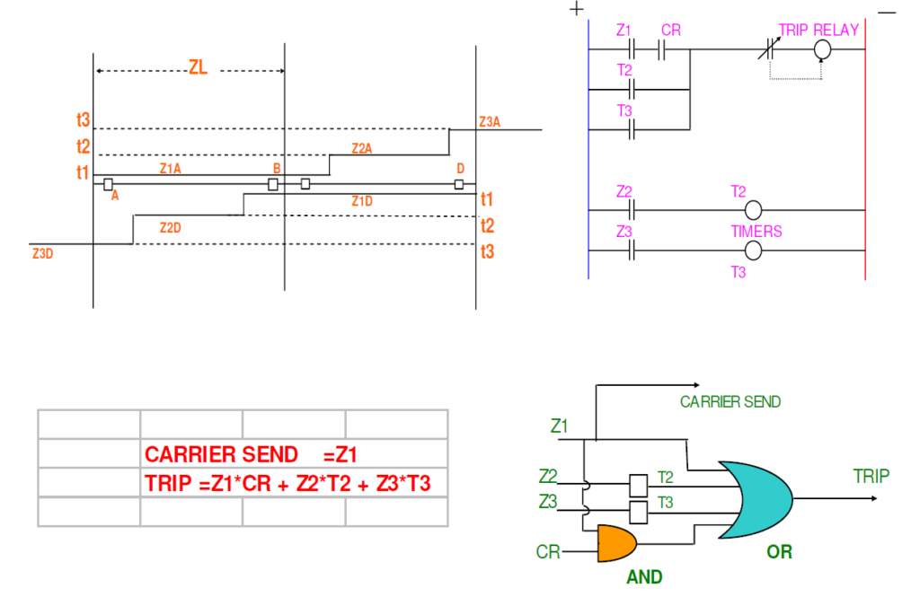
In this carrier aided protection scheme, the distance relay at one end of the protected lines sends a carrier signal to the relay at the other end of the line for inter-tripping, thereby clearing the faults on the entire line instantaneously.
Transfer trip is of two types: –
i) Under-reaching scheme: –
The scheme in which the Zone-1 of the relay covers about 80% of the impedance of the line and is used to send a signal to the remote end of the feeder for inter-tripping is called a transfer trip under-reaching scheme. To avoid mal-operation due to receipt of a false signal, the receiving end relay operation is interlocked with its Zone-3/starter operation i.e. the scheme operates either by a fault in the protected section and Zone-1 relay operation or on the receipt of carrier signal from the remote end relay, and its Zone-3/starter operation.

ii) Over-reaching scheme: –
This scheme is suitable for short lines where the use of underreaching Zone-1 will be too short to be of any practical use. In this scheme, the relay set such that it’s reach is beyond 100% of the line, and it sends an inter-tripping signal to the remote end of the line on the occurrence of the fault in the protected zone. It is essential that the receive relay contact be monitored by a directional relay which will ensure that tripping does not take place unless the fault is within the protected zone.

The absence of an independent Zone-1 tripping is a significant disadvantage in this scheme. The fast tripping therefore relies entirely on the signalling channel.
The disadvantage of carrier aided protection schemes is that the signal is transmitted over the fault line section. Distortion of the signal may occur due to introduced attenuation by the fault into the line.
BLOCKING SCHEMES: –
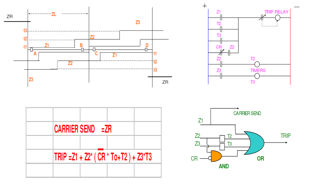
In this part of the carrier aided protection scheme, a blocking signal is sent by the reverse-looking directional unit ZR to prevent instantaneous tripping for Zone-2 & Zone-3 faults, external to the protected line. Here ZR must operate faster than forward-looking Zone-3 units and the signalling channel must also be extremely fast in operation.
Operational Comparison of Transfer Trip and Blocking Schemes
The blocking scheme works best for the protection of transmission lines with auto-reclosures enabled. The relay operates for end-zone faults in the blocking scheme even when there is a failure of the carrier signal.
But in the case of the transfer trip schemes, the relay won’t operate instantaneously for end-zone faults when there is a failure of the carrier signal.
The major advantage of a permissive transfer trip scheme is the high speed. In blocking schemes, there are intentional time delays for ensuring the receiving of the carrier signal. In transfer schemes, such intentional time delays are not present. The carrier acceleration scheme hence is much economical compared to the carrier intertripping and carrier blocking schemes.
Even during internal faults, sufficient fault current may not flow through a low fault current end terminal for the operation of the protective relay. However, the breaker at this low end has to be opened because even this low fault current can potentially maintain the fault.
To maintain stability and achieve high-speed auto-reclosing, the breakers at both ends of the line therefore must trip simultaneously. In permissive under-reach and acceleration schemes, the zone 1 relay at the high-fault current terminal does not see endzone faults. The relay at the other end terminal does not operate for the low fault and hence the carrier signal is not transmitted from the weak end. Therefore, these protection schemes are not suitable for use in such lines.
Attributes of an ideal carrier channel
- The delay involved in the communication should be small. At the frequency of 50 Hz, the delay should be much less than 20 milliseconds.
- High bandwidth is not required as only small information is to be transmitted
- The performance of the carrier channel must not be affected by power system faults
- The carrier channel should be hackproof and must be under the utility’s watch
- The carrier instruments like transmitters and receivers must be safe from the high voltage of the lines
- The carrier channel should be economical to operate.
FAQ’s
What is a carrier aided protection scheme?
Carrier aided protection scheme is a type of protection scheme intended for the protection of transmission lines in which the breaker at the local and remote end is operated simultaneously in the occurrence of fault between them via transmission of trip signal from the local to the remote end or vice versa with the help of a carrier communication channel.
What are PUTT, DTT and POTT?
In Carrier aided protection PUTT refers to Permissive Underreach Transfer Trip and POTT refers to Permissive Overreach Transfer Trip. DTT in carrier aided protection refers to a Direct Transfer Trip.
The article, “carrier aided protection” is a part of the Protection System, where other articles related to the protection of electrical equipments are discussed in details.

