The burden of current transformer is basically the apparent power that is consumed at the secondary side at a specific power factor, rated secondary voltage, and current. It is because of the impedance/ admittance at the secondary circuit expressed in Siemens or ohm and power factor.
Table of Contents
Unlike a normal transformer, a Current transformer’s secondary cannot be kept open-circuited because extremely high voltages that will be developed in the secondary, will eventually induce thermal and mechanical stress, leading to core distortion and failure. So a CT secondary is always connected to a continuous load, which acts as a burden.
CALCULATION OF BURDEN OF CURRENT TRANSFORMER’S CORE
The burden of the current transformer is expressed in Volt-amps or VA.
We know that voltage, V = current (I) * Resistance (R), And the amps in VA are also current (I) Therefore, the burden of the current transformer’s core, VA can be written as =(IR)*I , Which is equal to I2 R.
The current transformer in case of a LT panel installation will have a rated secondary of 5A but those used in the high voltage substations have a rated secondary of 1A as discussed in the previous article ACCURACY CLASS OF CURRENT TRANSFORMER easy explanation 121.
The metering core of the current transformer will be connected to a multi-function meter or MFM or energy meter via wires. Therefore, the connected burdens are due to the resistance of lead wires and the external burden of the meter.
BURDEN OF CURRENT TRANSFORMER = BURDEN OF LEAD WIRES + EXTERNAL BURDEN OF METER
BURDEN OF LEAD WIRES:
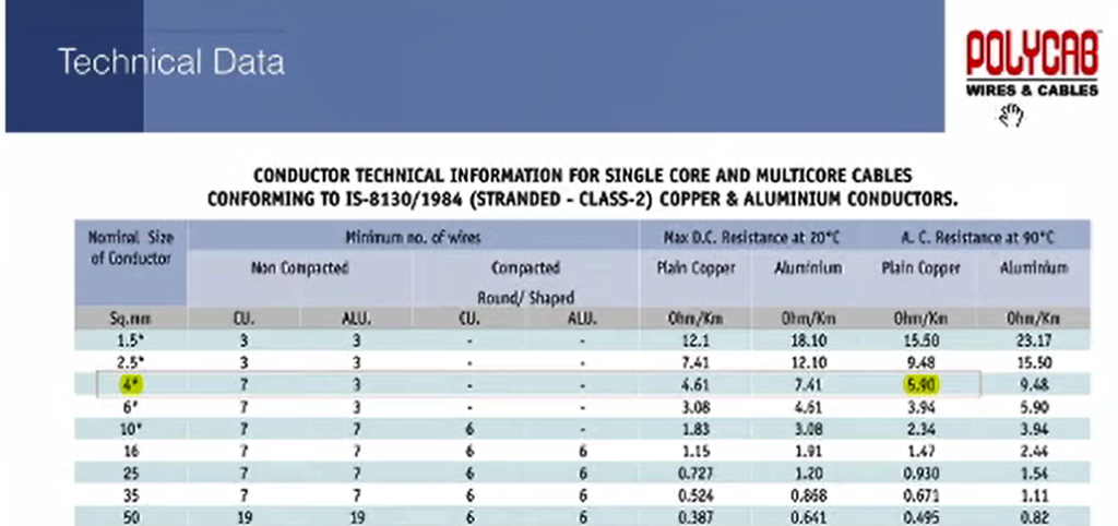
In general practice, we use 4-6 mm2 cables for this purpose. In the case of high voltage installations, the current transformers are placed outside in the switchyard, and the MFM or energy meters are installed in the control room of the substation.
This connection via lead wires will have a resistance that can be found in the cable manufacturer’s catalog. The resistance will be in ohm/km, we shall convert it to the desired length in our project/installation.

The lead wire burden is calculated as = I2 (2Rc), where I is the secondary rated current of the Current transformer’s core and Rc is the cable resistance. We multiply the cable resistance with 2 because the cable from CT to MFM has 2 number of runs.
EXTERNAL BURDEN OF METER
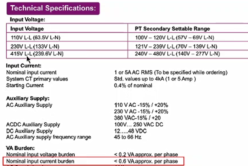
The burden of the energy meter connected to the secondary of the metering core of the Current transformer can be obtained from the manufacturer’s catalog or technical data sheet. Which is shown below.

Therefore, the burden of the current transformer’s metering core is equal to:
I2 2Rc + (VA)connected meter
It is to be noted that the designed burden of the current transformer must be greater than the calculated burden. Otherwise, the CT core will go into saturation quite often which is not desirable. Often we will have to use some margins however to match the market availability.
Some consultants also use the CT secondary winding resistance in the burden calculation. If we take into consideration the formula will change to:
I2 (2Rc + RCT) + (VA)connected meter, where RCT is the winding resistance of the CT. The winding resistance can be obtained from the CT manufacturer.
However, the consideration of CT winding resistance is another perspective, but the above formula for the calculation of burden is more popular in the industry.
It may also be noted that Current transformers used in substations have different cores for different purposes, like metering, and protection. Therefore, the calculation of burden is different for different cores of CT.
The lead resistance calculation will remain the same, however, the connected meter in case of metering core or relay in case of protection core will change as per core specification. Similarly, the burden of the current transformer’s cores will be calculated.
Significance of burden of current transformer
- Excessive burden of the CT can cause a shift of the operating point in the magnetization curve, which will hamper the accuracy of the current transformer by increasing the error.
- The burden of current transformer should be maintained low so that the CT is not saturated at the rated current.
- The burden of current transformer should be properly calculated to avoid the formation of very high voltages at the CT secondary which can damage the connected equipment at the CT secondary.
- To lower the burden of current transformer, the first method that can be applied is to make a reduction in the lead length, the shorter the lead length, the less will be the burden of current transformer.
This article is a part of the Transformer page, where other articles related to the topic are discussed in details.

