Potential Transformer:
A potential Transformer or voltage transformer is a type of instrument transformer that is used to step down the voltage from a higher level to an optimal level where it can be measured safely. It has higher turns in the primary winding and a smaller number of turns in the secondary winding. The primary winding is connected between a phase and the ground. For reducing the leakage reactance, co-axial winding is used here. For reduction of insulation cost the primary winding is divided into sections which reduce the insulation between the layers.
Any electrical equipment is sized based on its operating voltage. The higher the voltage, the more insulation will be used for a safe operation. The usage of more insulation thus adds to the cost of the equipment and size of the equipment. That means the bulkiness of the equipment will be more for high voltage.
Table of Contents
Moreover, it will not be safe to keep a measure of the instrument at such a high voltage level.
For the sake of ease of measurement at a lower voltage by rated voltmeters/potentiometers we use a potential transformer, which by means of electromagnetic induction is able to step down the voltage to a measurable range.
Connection:
The primary winding is directly connected in parallel to the high-voltage circuit, whose voltage is to be measured. The secondary terminals are connected to voltmeters/wattmeters, protection relays, etc. The secondary winding is magnetically coupled to the primary winding just like other transformers.
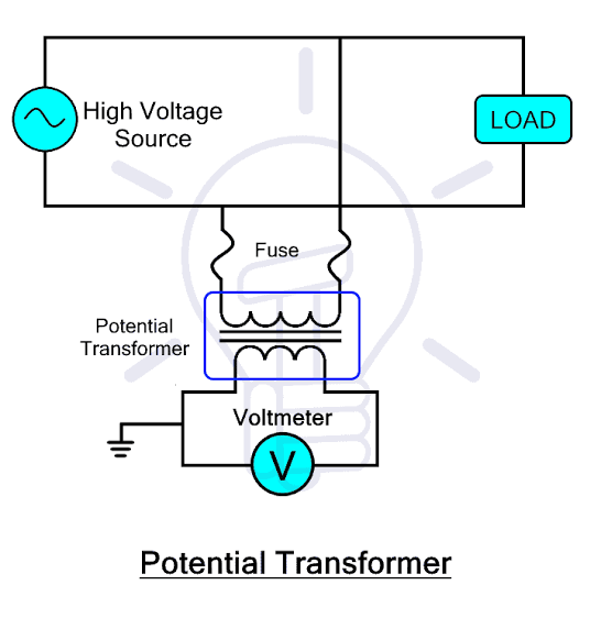
Normally the rated secondary voltage of potential transformers is 110V, the primary may be rated anywhere between 11KV and 800KV.
Burden:
The burden of Potential Transformer is the total external volt-ampere load connected to its secondary. The rated burden must not be exceeded if the transformer has to operate with rated accuracy. The rated burden is indicated in the nameplate. Normally we use 50VA per winding.
The limiting burden is the maximum VA load at which the PT will operate continuously without overheating the windings beyond permissible limits. The limiting burden is many times the rated burden.
Errors in Potential Transformer:
In an ideal condition, the primary voltage is exactly proportional to the secondary voltage which is at exact phase opposition. But in actual practice, there exists a voltage drop and it leads to ratio error and phase angle error of the Potential Transformer.
Ratio Error:
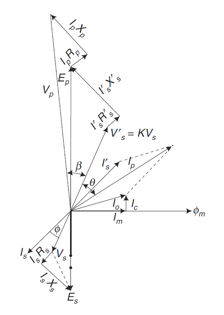
Es = Secondary induced voltage
Ip = Primary current
Is = Secondary current
Rp, Xp = Primary resistance and leakage reactance respectively
Rs, Xs = Secondary resistance, and leakage reactance.
Io = VT primary excitation current
Im = Magnetizing component of the exiting current I0 required to produce flux
Ic = Iron (core) loss component of the exciting current I0 supplying core losses.
V’s = Secondary terminal voltage referred to the primary side = ktVs
I’s = Secondary current referred to primary side = Is/Kt
R’s = Secondary resistance referred to primary side = K2 Rs
X’s = Secondary leakage reactance referred to primary side = K2 Xs
Z’b = Secondary burden referred to primary = K2 Zb,
Φ = Phase angle of the burden
β = Phase angle error = Angle between Vp and reversed secondary voltage, V’s
θ = Angle between V’s and Ip
Φm = Core flux
Just like the Current Transformer, the total primary current, Ip in a voltage transformer is proportional to the vector sum of the excitation current, Io, and the reversed secondary current, Is.
i.e. Ip = (Io + Is) / Kt, where Kt is the turns ratio of the transformer.
and Kt = Np / Ns
If Vp is the system voltage applied to the primary of the PT then voltage will drop in the primary because of resistance and reactance in the primary winding due to primary current Ip. After considering this voltage drop, Ep, the primarily induced emf will appear across the primary terminal which will transform to Es, the secondary induced emf in the secondary terminal because of mutual induction.
Again Es will be further dropped because of resistance and reactance in the secondary winding and will result in Vs which will appear across the burden connected to the secondary.
So, if Vp is the primary voltage, Vp/Kt should have been the secondary voltage of the Potential Transformer but in practice, it is always Vs.
Therefore the voltage error or the ratio error of Potential Transformers is the difference between the ideal secondary output (Vp/Kt) and actual secondary output (Vs)
% voltage error = (Vp -Kt * Vs) / Vp * 100%
Phase Angle Error:
The phase angle between primary system voltage Vp and secondary output voltage Kt * Vs which is in exact opposition is known as the phase angle error of PT. The increase in a number of instruments or relays connected to the PT secondary will increase this error.
Application:
- It is used for stepping down the voltage for ease of metering.
- It is used for the protection of feeders
- It is used for the protection of generators
- It is used for the protection of transformers
- It is used for the synchronization of generators and feeders.
- It may be noted that Potential Transformers cannot measure or protect anything singly. It only aids in providing the low output voltage which can be easily measured and provides low voltage output signals to various relays which then with the different protection schemes, protect equipment and power system from various faults.
Types of Potential Transformers:
The types of potential transformers are briefly discussed below:
Voltage Transformer:
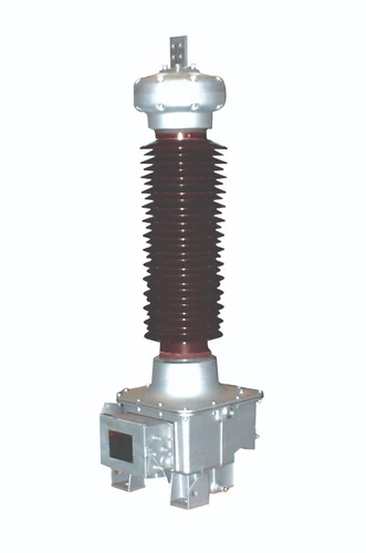
These are conventional wound-type transformers.
Capacitive voltage Transformers:
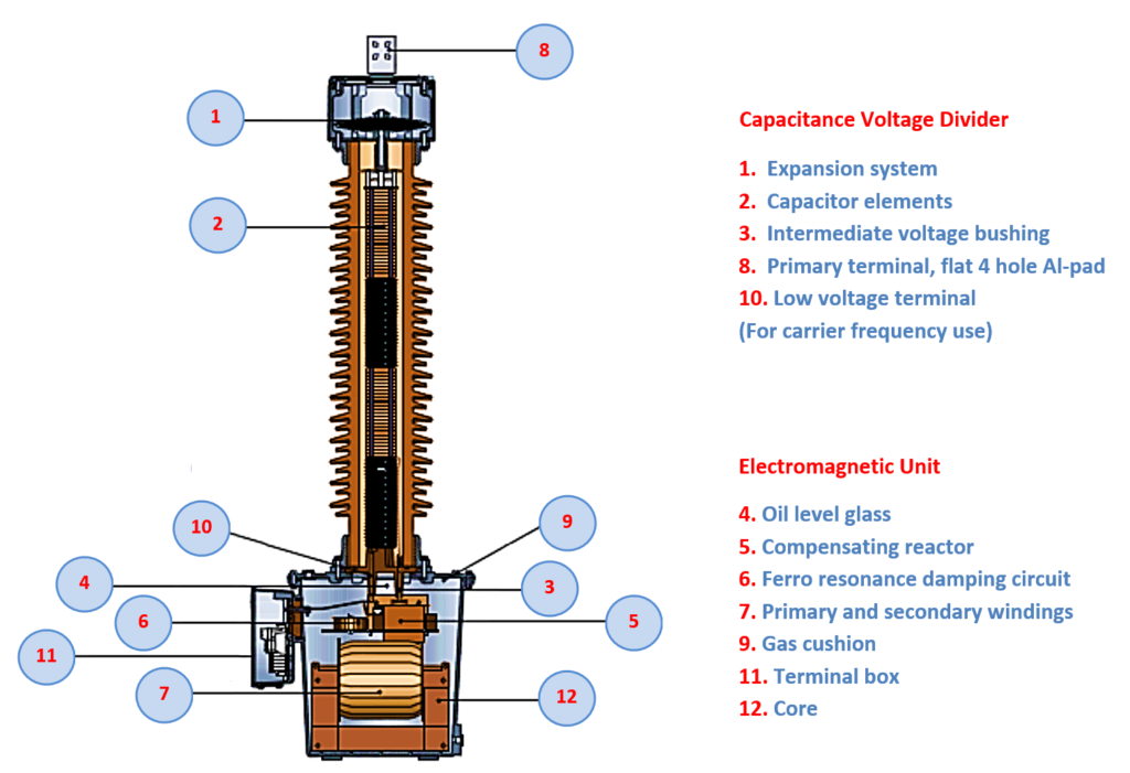
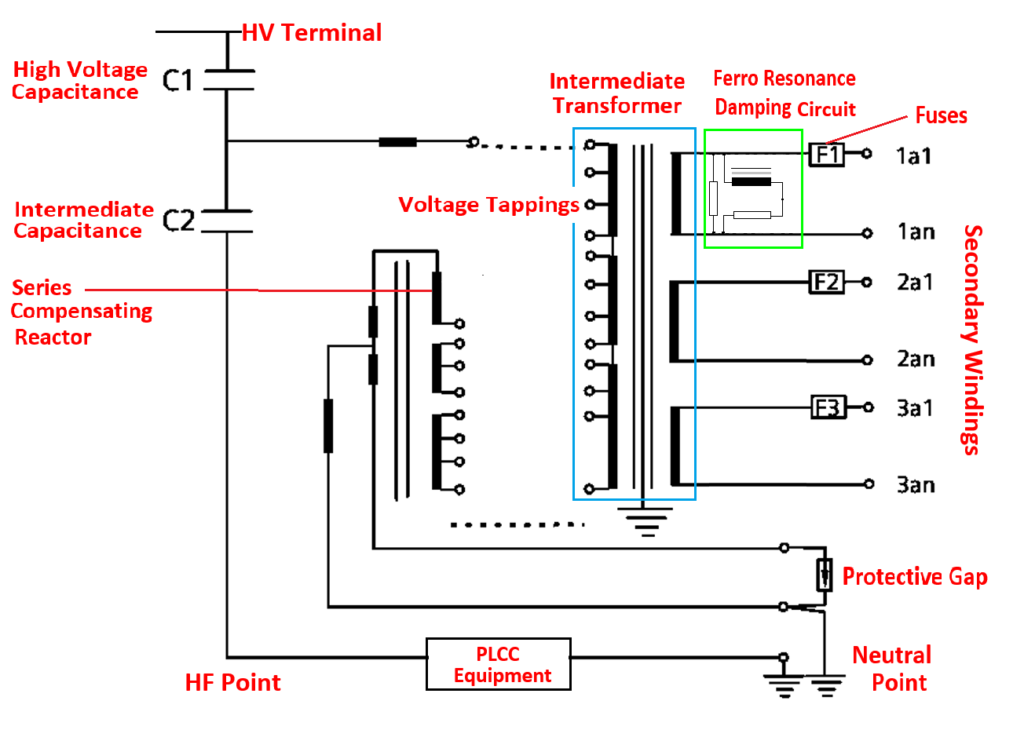
In CVTs, we generally take two capacitors C1 & C2 connected between line and ground. Normally a tapping is taken out from the capacitive coupling and connected to a voltage transformer element. As the voltage is divided between the capacitors, the number of turns required for the voltage transformer element reduces and the overall dimension of the equipment becomes less. It is mostly used for protection and carrier communication. Due to the insertion of capacitive elements phase shift occurs. However inductance is also used to counter that, it affects the accuracy of the VT element. It is normally used from a voltage range of 132KV to 765 KV.
Electromagnetic Voltage Transformer:
The electromagnetic voltage transformer or Inductive voltage transformer is the same as a voltage transformer. The accuracy of CVT is compensated because of two capacitive elements. The IVT’s accuracy is however more. Its circuit is the same as simple VT. It is used for revenue and tariff metering purposes in the range of 132KV to 765KV levels.
Dual purpose VT
It is a voltage transformer that has one magnetic core but is used for both metering and protection.
Residual VT
A three-phase or a group of three single-phase VT, having windings connected in an open delta connection so as to produce a voltage proportional to the residual voltage that exists in the three-phase system. A normal VT has 3 limb cores but a residual VT has 5 limb cores for the return path of residual flux.
Earthed VT
A single-phase VT whose one end of the primary winding is connected to the earth is known as an earthed VT. For a three-phase star-connected VT, the star point is taken out and earthed.
Difference between CVT and VT
| Aspects | CVT | VT |
| Components | CVT has a capacitor voltage divider and a step-down transformer to reduce the high voltages. | VT makes use of step-down transformer only for reducing the high voltages. |
| Working principle | Voltage division between capacitors and electromagnetic induction. | The working of a VT is only based on the principle of electromagnetic induction. |
| Voltage step-down process | A CVT first reduces the voltage using a capacitor voltage divider and then this reduced voltage is further stepped down using a step-down transformer. | A VT reduces the voltage using a step-down transformer only. |
| Core losses | VT makes use of a step-down transformer only for reducing the high voltages. | Losses are more compared to CVT |
| Coupling of PLCC | Due to small sized magnetic core, CVTs have losses. | VTs are not suitable for communication. |
| Weight | CVTs can be used for coupling of PLCC as it has coupling capacitors and ferromagnetic circuits. | CVTs are lighter in weight due to their small core size. |
| Design complexity | VTs are relatively heavier and more bulky than CVTs. | VTs have a simple design as they use only an electromagnetic unit. |
| Effect of varied frequency | VTs do not have such issues. | CVTs have a relatively complex design due to the presence of an additional capacitor voltage divider. |
| Applications | CVTs are mainly used in extra-high voltage for metering protection and communication | Performance is affected by the variations in frequency because of the use of capacitors. |
Accuracy Class:
Multicore Potential Transformers are used in the power industry. That means one piece of equipment will have more than 1 core. One is used for metering, the other for protection, and one may be left for spare use.
Accuracy means the percentage of error present in the VT at 80-120% of the rated output voltage.
0.2 class is used for metering.
3P class is used for protection.
Here 3 is the 3% error and P stands for protection class
As voltage is mostly constant and does not fluctuate like current, we do not use 0.2s class & 0.5s class for metering.
Protection of Potential Transformers
Potential transformers also known as voltage Transformers can be protected by H.R.C. fuses on the primary side for voltages up to 66kV. Fuses do not usually have a sufficient interrupting capacity for use on the higher voltages. Therefore, the practice varies, and in some cases, protection on the primary is omitted.
The secondary of a Potential Transformer is always protected by fuses or a miniature circuit breaker (MCB). The device is located in the control panel.
A short circuit on the secondary circuit wiring will produce a current of many times the rated output and cause high heating. Even where primary fuses can be fitted, these will usually not clear a secondary side short circuit because of the low value of primary current and the minimum practicable rating of the fuse. Therefore, the secondary circuit’s fuse or MCB is the only protection of VT’s secondary circuit.
Common issues with PTs in substations
- Insulation failure: Basically caused due to aging, and moisture, leads to short circuit by the breakdown of dielectric strength.
- Secondary Open circuit: Loose connections, broken wire, or blown-out fuse may cause a secondary open circuit. Although it is not as detrimental as in the case of a CT, however, care is still needed as it will disrupt the metering since no voltage will be fed to the meters and also the protection will malfunction due to the same.
- Phase Error: Aging or core saturation induces the phase error which leads to differences in the voltage reading affecting the metering and protection.
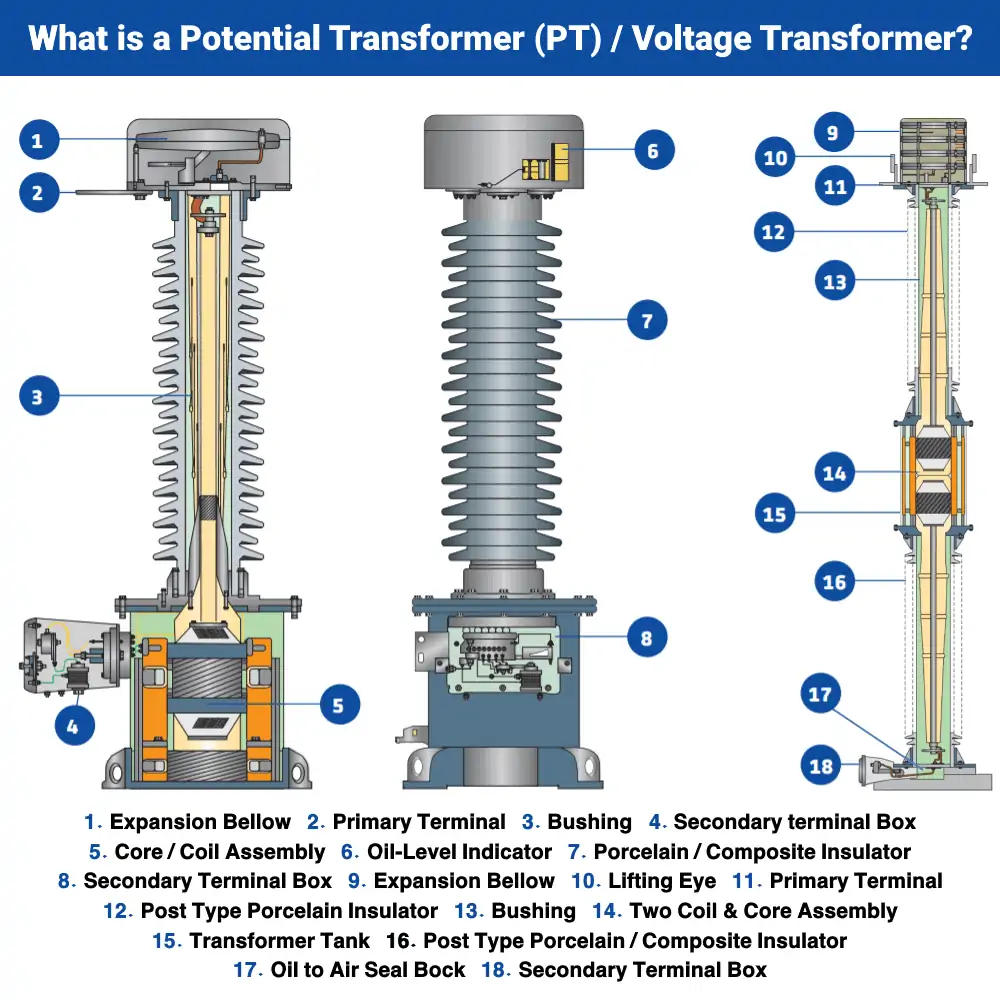
- Oil leakage: Oil leakage in the PTs is caused by the failure of gaskets due to corrosion. It can lead to insulation failure by the ingress of moisture upon low oil level. Hence, the oil level must be maintained up to a minimum marked level on the oil level indicator situated at the top of the PT.
This article is a part of the Transformer page, where other articles related to the topic are discussed in details.

