A lightning arrester is a protective device which conducts or diverts the harmful high voltage surges on the power system safely to the ground. It is the frontline warrior used for the protection of equipment against the travelling waves and overvoltages in the overhead transmission line.
Though the earthing screen and ground wires provide protection to the electrical system against direct lightning strokes, they cannot provide protection against the indirect travelling waves resulting from lightning strokes or switching surges which can potentially reach the terminal of the electrical apparatus causing damage. The lightning arresters or surge diverters thus provide protection against such surges.
Table of Contents
Overvoltage starts in the form of the travelling wave from the start point and works as a heavy stress on the insulation of any equipment because they are above the equipment’s normal rated voltage. Therefore, the quick discharge of these over-voltage spikes is necessary to protect the equipment and this discharge facility is achieved by the use of a surge arrester.
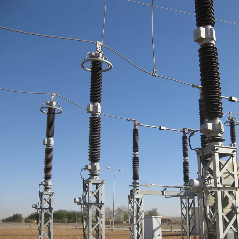
Surge arresters or LA are voltage-limiting devices used to protect the electrical insulation from voltage spikes in a power system. Its job is to protect the system from damage basically due to over-voltage surges.
It may be noted that: –
- A lightning arrester does not soak up the lightning surge but engages it to the ground.
- It does not stop lightning.
- It does divert the high-voltage lightning surges to the ground which if not grounded can potentially damage the connected equipment.
- It limits the voltage produced by lightning or switching by diverting the extra voltage to the ground.
- It protects equipment which are connected electrically in parallel with it.
- It does protect the line or connected equipment from indirect lightning surges and switching surges. However, it does not offer protection from direct lightning.
- A lightning arrester is placed in the entry and exit of a transmission line in a substation.
- They are also placed next to a transformer and reactor to protect them from switching surges.
- As the terminal of lightning arresters has no switching action, therefore, at the terminal, the voltage gradient is built up.
We use the corona control ring to: –
- To reduce the corona discharge.
- To distribute the voltage uniformly.
According to research in electrical substations with voltage levels including and greater than 220KV, switching surges are more severe as the surge duration is high. Therefore the lightning arrester there is called a surge arrester. And in substations at a lower voltage level than 220KV lightning surges are more severe, therefore the surge diverters are called lightning arresters.
Working Principle of a Lightning Arrester
In its basic form, the lightning arrester consists of a number of disc-shaped metal oxide blocks, stacked one above the other. These varistor blocks work by opposing the rated power frequency voltage meaning the varistor blocks offer resistance to the flowing current at the rated voltage.
But when there is a lightning surge or a travelling switching surge, there is a rise in the voltage level above the rated because of the transient. At this high voltage, the varistor blocks turn conductive and provide an unopposing grounding path for the current, diverting the current successfully to the earth. This helps prevent the damage of equipment from sudden excessive voltage spikes. As the transient fade in the next couple of cycles, the voltage returns back to normal or at or below the rated voltage level, and the varistor blocks turn resistive, resuming the normal operation.
Overvoltages other than lightning and switching
Apart from lightning and switching surge, the lightening arrester or surge arrester also provides protection against the following temporary overvoltages:
Overvoltage due to Earth faults:
These overvoltages occur in a large part of the system. The duration of the over-voltage corresponds to the duration of the fault (until fault clearing). In systems with the neutral earthed, the duration is generally less than 1 s. In resonant earthed neutral systems with fault clearing, mostly adopted in distribution networks, the duration is generally less than 10 s. In systems without the earth, the duration may be several hours.
Overvoltage due to Load rejections:
After the disconnection of loads, the voltage rises at the source side of the operating circuit breaker. The amplitude of the overvoltage depends on the disconnected load characteristics and on the short-circuit power of the feeding substation.
Other Causes of temporary overvoltage
The causes of temporary overvoltages which also need consideration are as follows:
- resonance effects, e.g. during initial charging of long unloaded lines or resonances between systems,
- voltage rise along the long lines (Ferranti effect),
- harmonic overvoltages, e.g. when switching transformers,
- back feed through interconnected transformer windings, e.g. dual transformer station with a common secondary bus during fault clearing or single-phase switched three-phase transformer with an unbalanced secondary load.
Types of Lightning arrester:
There are many types of lightning arresters which are in general use. The difference between the various types is only in the constructional details but they operate on the same principle which is providing a low reactance path for the surges of higher voltage than the rated, to the ground.
Rod gap arrester
It consists of two rods of 1.5 centimetres that are bent at right angles. One rod is connected to the line circuit and the other rod is connected to the earth. The distance between the gap and the insulator (length P) must be equal to or greater than one-third of the gap length.
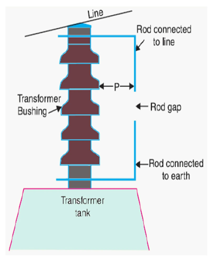
Generally, the length of the gap is adjusted so that breakdown occurs at 80% of the spark-over voltage. Under normal operating conditions, no conduction of electricity occurs between the gap.
As a high voltage surge occurs on the line, the spark fills the gap, creating a low reactance path so that the surge current is conducted or engaged to the earth.
Horn Gap Arrester
Horn gap arresters have two horn-shaped rods made of metals which are separated by a small air gap. The horns are so constructed that the distance between them gradually increases towards the top. The horns are mounted on porcelain insulators. One horn is connected to the line in parallel to the equipment to be protected through a resistance R and choke coil L, the other end is grounded effectively. The resistance R limits the flow of current to a small value.

The choke coil is so designed that it offers a small reactance at normal power frequency but a very high reactance at transient frequency.
Thus, the choke does not allow the transients to enter the equipment connected in parallel. The gap between the horns is so adjusted that the normal supply voltage is not enough to cause an arc across the gap.
Multigap arrester
Multigap arresters basically consist of a series of metallic (generally alloy of zinc) cylinders that are insulated from each other and separated by small air gaps. The first cylinder (A) is connected to the line and the other to the ground through a series resistance. Under normal conditions, the point B is at ground potential and the normal available voltage fails to break down the series gaps.

On the occurrence of an over voltage, the breakdown of series gaps A to B occurs. The high current after the occurrence of breakdown, chooses the straight path to earth via the shunted gaps B and C, instead of the alternative path through the shunt resistance. When the surge is over, the arcs B to C go out and the arcs in the gaps A to B and normal conditions are restored.
Expulsion type arrester
This type of arrester generally consists of a rod gap as shown in the figure. The rod gap is in series with an internal air gap that is enclosed within a fibre tube. The internal air gap in the fibre tube is formed by two electrodes out of which one electrode is connected to the rod gap and the other electrode is grounded.
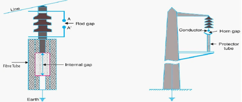
When the overvoltage occurs on the line, the rod gap is filled up by an arc also an arc is formed in the fibre tube since the rod gap and the internal gap of the tube are in series. The heat from the arc vaporises a tiny bit of fibre from the fibre tube’s wall, and a neutral gas is generated in the process. In an extremely short time, the high pressure builds up inside the tube by the gas and is expelled through the lower electrode which is designed hollow. The gas while leaving the the tube violently, carries away the ionised air around the arc.
The de-ionising effect is so strong that the arc gets blown out at a current zero by the gas leaving the tube and fails to re-establish.
Valve-type arrester:
It consists of two assemblies of series spark gaps and discs of non-linear resistors which are made of thyrite or metrosil in series. The non-linear elements are also connected in series with the spark gaps inside the porcelain housing. Both assemblies are accommodated in tight porcelain containers. The electrical resistance in the disc decreases as the current through them increases and vice-versa. Under normal operating conditions, the system voltage is insufficient to cause a breakdown of the air in the gap.
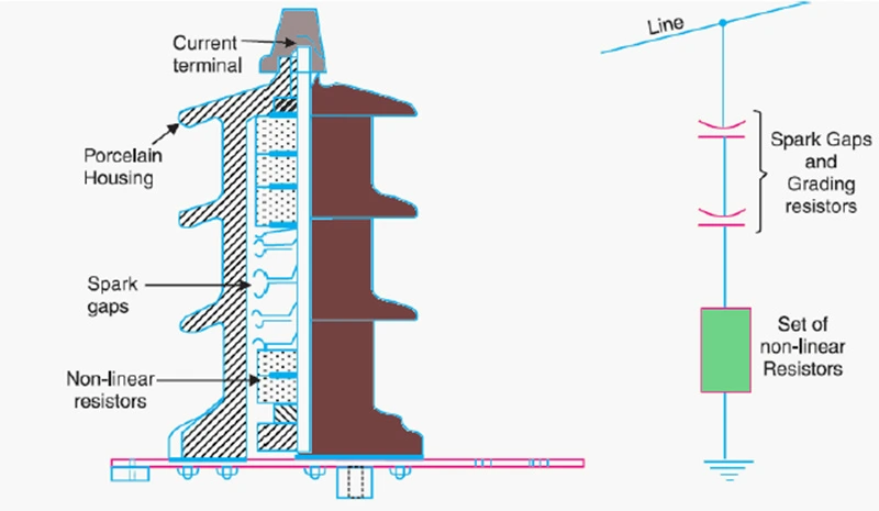
But, when the overvoltage occurs, the air between the gap breaks down forming an arc which conducts the surge current to Earth via the non-linear resistors. When the transient is over, the non-linear resistors get back the high resistance to stop the flow of current.
Metal-Oxide Surge Arresters (MOSA)
A metal-oxide surge arrester contains non-linear metal–oxide resistive disc elements with excellent heat-withstanding capabilities. Each disc is made of powdered zinc oxide material mixed with other metal oxides. This type of surge arrester works like a high-speed switch – opened at rated voltages and closed at over-voltages.
Zinc oxide lightning arresters are highly non-linear – their non-linear characteristic is much more pronounced than that of silicon carbide – and have low losses under steady-state conditions, due to very little leakage current.
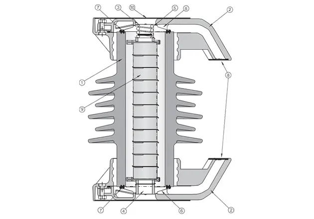
Image courtesy ABB
| 1 | Porcelain insulator | 6 | Sealing cover |
| 2 | Venting duct | 7 | Sealing ring |
| 3 | Spring | 8 | Indication plates |
| 4 | Desiccant bag | 9 | ZnO-blocks |
| 5 | Copper sheet | 10 | Flange cover |
There are three types of metal-oxide arresters:
- Gapless
- Series-gapped
- Shunt-gapped
Gapless metal-oxide lightning arresters are of particular advantage for earthed neutral systems as they offer better protection against slow-front overvoltages. This arrester type is today widely installed in these systems and the application of arresters for such systems tends to concentrate on metal-oxide surge arresters.
In some isolated or resonant earthed neutral systems, where earth fault temporary overvoltages may have long durations, gapped lightning arresters offer the advantage if protective levels are required to be low. While the lightning arrester is traditionally used in all voltage ranges, the consideration of gapped arresters may be adequate for systems, especially in the lower voltage range.
Gapless zinc oxide lightning arresters are mostly used nowadays as it is economical and can handle large amounts of energy.
Upto 220KV voltage the energy handling capacity of a lightning arrester is suggested to be around 5KJ and beyond 220KV, 12 KJ is suggested as per IEC standards.
Surge Arrester Classification and Application
- Maximum continuous operating voltage: The maximum continuous operating voltage across the arrester is the voltage which the arrester can continuously withstand without discharging to the ground. Since the arrester is connected between phase and ground, MOCV = Max Line Voltage / √3. For example, a 33KV Lightning arrester’s MCOV will be = 36/√3 = 20.78 KV. Note: The offered MCOV value by the vendor should not be less than the calculated, which in this case is 20.78 KV.
- Rated voltage: The rated voltage of the arrester (Ur) is = [Max line voltage x √2] / √3. The main concern of selecting the rating is that the arrester will be subjected to the line-to-ground dynamic voltage for any condition of the system operation. It may be noted that this holds true for Y-solid grounding. In case of NGR grounding, the limited current will boost up the voltage and phase voltage will not be equal to line voltage VL/√3. Therefore, in this case the LA voltage should be higher than the line voltage.
- Discharge current through the arrester: The discharge current preferred are 20KA for 400-765KV, 10 KA for 33-220KV and 5KA for distribution voltage systems as per the IEC.
- Long duration discharge class: It is a stress test class of the arrester which represents the ability of the arrester to discharge multiple high-energy impulses over longer durations in milliseconds repeated over a specific time without failing. As per industry norms, class 5 lightning arresters are used in 765KV substations, class 4 in 400KV, class 3 up to 132KV levels. For the 33KV level class 2/3 can be used as per tender specification and class 1 is used in distribution voltage levels.
- Pressure relief fault current: Suppose the lightning arrester fails to discharge the surge carefully to the ground, then due to the line-to-ground arc that develops inside the arrester will cause the pressure build up inside the LA housing. The Lightning arrester should handle this pressure and because of this, it is designed for pressure relief fault current capability. In this case, the system fault current is considered as the peak pressure relief fault current for the arrester. However, the overvoltage surge may also generate pressure inside, to handle this, the arresters are fitted with pressure relief devices to counter explosive shattering of the LA housing.
Based on voltage rating, characteristics, and the durability in pressure-relief or fault withstand characteristics, the classification of surge arresters generally used is as follows:
Station arresters:
These arresters give the best protective levels with lower discharge voltages, higher rate of energy absorption, and the most significant pressure relief. Typical applications are in High voltage substations and equipment.
Intermediate arresters:
Have inferior protective characteristics and energy discharge capability compared to station class. Used for Medium voltage applications for small substations, underground cable protection, and dry-type transformers.
Distribution arresters:
These arresters give the lowest protective levels with low energy discharge ability. They are used in pole-mounted substations for the protection of distribution transformers up to and including 15KV classification.
Constructional features essential in substation
- The LA should be hermetically sealed.
- The surge monitor of the LA should be tested for IP66 degree of protection because of outdoor installation.
- The surge monitor should be 1.4 to 1.8 m above the ground.
- Potential free contacts should be provided in the surge monitor for integration with the substation SCADA.
This article is a part of the Protection System, where other articles related to the protection of electrical equipments are discussed in details.

