Local breaker backup or LBB protection is a circuit breaker failure scheme that operates to protect a faulty circuit when the associated circuit breaker fails to trip, by tripping all other circuit breakers associated with the bus bar. Thus, isolating the faulty circuit.
Table of Contents
A circuit breaker functions to clear the faults in the system or remove the abnormalities by isolating the faulty circuit from the system. Circuit breakers interrupt the fault current when it receives a trip command from the protection system that has detected the abnormality or an electrical fault. But the circuit breaker is also prone to faults and can fail to operate and break the fault current. These can then cause massive abnormalities in the power system as the fault current can cause the failure of equipment.
In research conducted by Cigre, it has been found that in 0.94% of every 10,000 first inquiries and 0.24% of every 10,000-second inquiries, the circuit breaker fails to open and break the fault current. It is because of this the LBB has opted to add a second layer of protection in case the circuit breaker fails to operate.
LBB is a protection scheme that is designed to clear a system fault by initiating a tripping signal to other associated breakers to the breaker that has failed to operate. In modern power networks, the critical fault clearing time is less than 200ms. Hence, if the fault is not cleared due to failure of the circuit breaker then a fast-acting backup protection scheme must clear the fault.
As the cost of the high-voltage circuit breaker is higher, duplicating the breaker in a circuit is not a feasible proposal. Therefore, all the circuit breakers associated with that bus must be tripped in order to stop the fault from propagating into the system.
LBB PROTECTION EXAMPLE

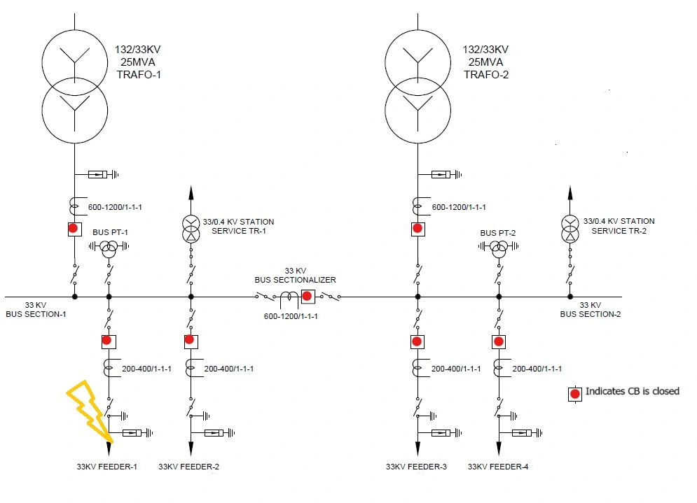
Let us suppose that there is a fault in the 33KV feeder 1 and the associated circuit breaker fails to operate, then on LBB operation, all the circuit breakers associated with the 33KV bus will trip. In the above case, 33KV feeders 2,3,4 and the transformer’s LV side circuit breakers along with the bus sectionalizer CB will trip as a result of LBB operation. Thus, because of the LBB protection, the feeding of fault at feeder 1 will stop which otherwise would have been a catastrophe as high fault current would have been fed continuously until a circuit element or conductor or jumper associated with the faulty phase fails or ruptures.
LBB PROTECTION STAGES:
The Breaker Failure Protection (LBB/BFR) can operate single-stage or two-stage.
SINGLE-STAGE LBB PROTECTION:
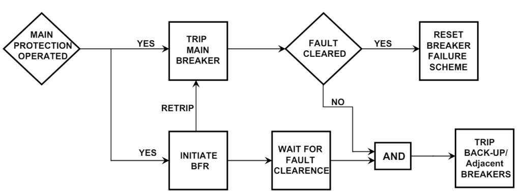
In the single-stage protection, the Bus trip command is given to the adjacent Circuit Breakers of the protected feeder if the main Breaker fails to operate.

TWO-STAGE LBB PROTECTION:
In the two-stage protection, the first stage is meant to repeat the trip command to the relevant feeder’s Breaker, normally on the other trip coil, if the initial trip command from the feeder protection fails to isolate the circuit. The second stage is intended to initiate a Bus trip to the adjacent Breakers if the command of the first stage fails.
LBB OPERATIONAL SCHEME:

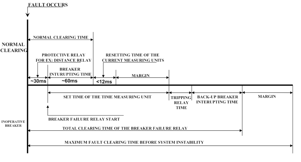
As the fault occurs, the sensing of the protective relays and sending of the trip signal to the master trip relay takes 30ms. At this time the LBB protection relay initiates. After that, the master trip relay sends the trip signal to the associated circuit breaker. The time taken to interrupt the fault or open the breaker is 60ms. Now if the breaker is successful in interrupting the fault the local breaker backup relay resets. If the breaker is unsuccessful and the fault persists, then LBB triggers a trip signal to all the breakers in the associated bus thereby tripping all the breakers and interrupting the fault. This is how LBB protection works to clear a fault.
- It takes 30 ms for the protective relays to sense and send a signal to the relay 86 master trip
- Another 60ms is taken by the breaker to interrupt the fault.
- Less than 12ms is taken by the current measuring unit of the protective relay to reset.
- The 60-80ms margin of time delay is taken for the initiation of the LBB trip.
- if the current measuring unit still senses the fault after its resetting time and is not reset, it will indicate the fault persisting in the circuit and the breaker has failed to interrupt the fault.
- After the margin, LBB initiates a trip signal to all associated circuit breakers to interrupt the fault and restrict its further propagation.
It may also be noted that the LBB protection scheme also provides protection to the faults that rarely occur between CB and CT which is often not covered by other protection schemes.
KEY POINTS OF LBB PROTECTION
- This relay is separate for each breaker and it is to be connected to the secondary circuit of the Current transformer associated with the breaker.
- For line circuit breakers, direct tripping of remote end breakers should be arranged on the operation of LBB protection.
- For transformer breakers, direct tripping of the breaker on the other side of the transformer should be arranged on the operation of LBB protection.
- For line breakers, employing single-phase auto reclosing, the LBB protection relay should be started on a single-phase basis from the trip relays.
- The CT secondary core used for LBB protection is preferred to be in a separate core. If that is not available, it shall be Clubbed in series with Main-1 or Main-2 protection.
- LBB protection relay cannot operate without proper initiation. It is therefore a good practice to provide redundant trip output and breaker failure input where other forms of redundancy do not exist.
- Good separation should be maintained between the protective relays and the CB trip coil’s DC circuit so that a short circuit or blown fuse in the CB circuit does not restrict the protective relay from energizing the LBB scheme.
- In addition to other fault sensing relays the LBB relay should be initiated by a Bus bar protection scheme, since failure of CB to clear a bus fault would result in the loss of the entire station if the LBB relay is not initiated.
- The tripping logic of the bus bar protection scheme shall be used for LBB protection also.
- Breaker-failure relaying for low energy faults like Buchholz operation, special considerations must be given to ensure proper scheme operation by using CB contact logic in addition to current detectors.
- Current-level detectors should be equally sensitive as the main protection. The commonly practiced setting for Lines and Transformers is 0.2Amp
- Setting of the timer must consider the inclusion of breaker interrupting time, current detector reset time, and a margin. Generally, a timer setting of 200ms is adequate in practice.
Conclusion:
LBB adds a layer of protection to the existing protection scheme of a bay in a substation. It increases the redundancy by ensuring swift and quick disconnection of faults. It helps minimize the cascading failure of the grid elements. Moreover, it adds to the safety of the operator and improves downtime helping in stabilizing the electrical grid. The design however may change in varying substations and can be configured as per the requirements of the grid elements and utility standards.
FAQs
What is the full form of LBB Protection?
The full form of LBB is Local Breaker Backup protection.
What is the ANSI code of LBB protection?
The ANSI code of LBB is 50BF.
What is the function of LBB?
LBB Protection functions to interrupt a fault by tripping all circuit breakers associated with a bus when the main circuit breaker fails to operate and interrupt the fault.
This article is a part of the Protection System, where other articles related to the protection of electrical equipments are discussed in details.

